Section 7: Sealed SystemsPage 24
7.6 15/26 SEALED SYSTEM KIT
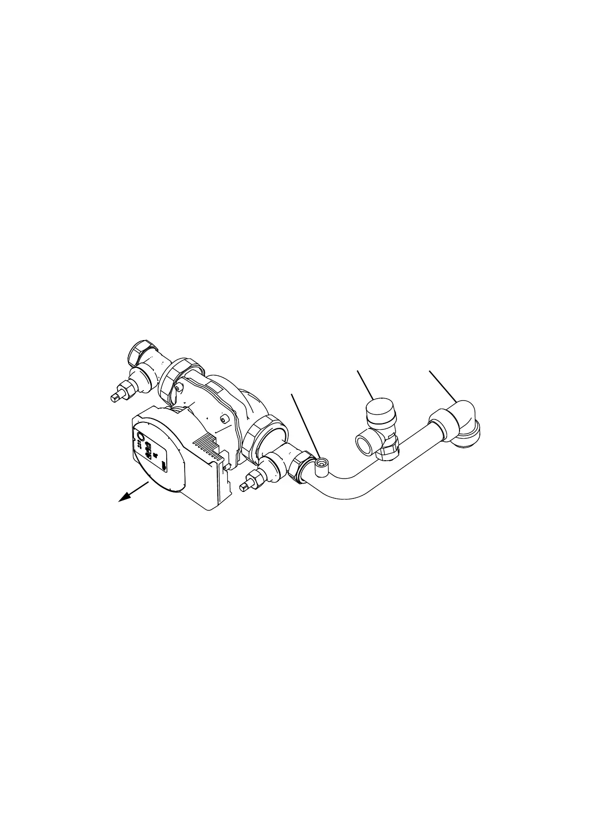
See Figure 7-8
1. The kit includes the following items:
• Pressure relief valve.
• Air vent.
• 22 mm manifold pipe.
• 12 litre expansion vessel with exible hose and sealing washer.
• Filling loop kit.
• Pressure gauge (mounted on compression tee).
• 7 m head circulating pump with connection lead.
• 2x 22 mm gate valves.
• 15 mm copper pressure relief valve discharge pipe (in two
pieces with push-t connector).
2. Remove the ½” BSP black iron plug from the front of the boiler
waterway, using a 3/8” drive socket wrench.
3. Fit the ½” BSP straight end of the exible expansion vessel hose
to the tapping on the front of the waterway using a suitable thread
sealant.
4. Position the 12 litre expansion vessel on the front of the boiler
combustion door locating the hook (on the back of the vessel)
onto the uppermost handle of the combustion door.
5. Fit the ¾” BSP connection of the exible expansion vessel hose
to the vessel using the black rubber washer supplied and tighten
the nut.
Front
of boiler
Manual
air vent
Pressure
relief valve
Push-fit
elbow
Figure 7-8: Vortex Pro External 15/26 sealed system kit pump assembly
(Wilo Para SC pump shown)
6. Push the 22 mm push-t elbow (supplied with the boiler) onto
the boiler ow pipe.
7. Fit the pressure relief valve onto the manifold pipe, then push
the manifold pipe end into the 22 mm push-t elbow on the
ow pipe.
Refer to Figure 7-8.
8. Fit both 22 mm pump valves to the circulating pump using the
sealing washers supplied.
9. Fit the pump assembly to the air vent/pressure relief valve
assembly ensuring that the pump shaft is horizontal and the
pump motor is facing towards the front of the boiler. The ow
arrow on the body of the pump must face in the direction of
ow away from the boiler connection.
10. Fit the pressure relief valve discharge pipe to the pressure relief
valve using the nut and olive supplied. Route the discharge pipe
through the slot in the base of the right hand side panel. Push
the panel insulation back to expose the slot.
11. The circulating pump may be wired into the boiler control
panel if required. Refer to Section 8.
12. The pressure gauge and lling loop should be installed in a
convenient position inside the building.