Section 7: Sealed Systems Page 23
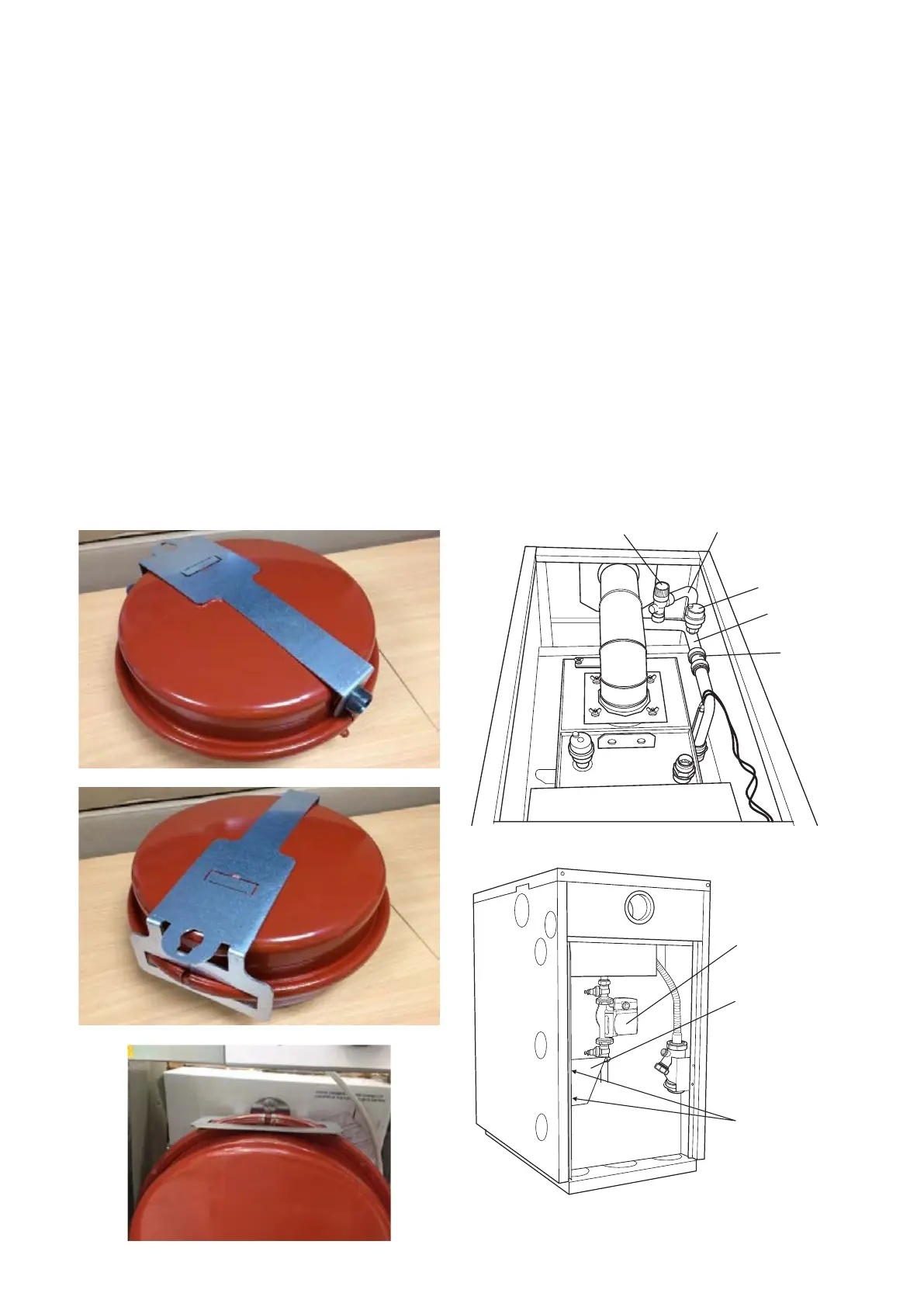
6. Fit the expansion vessel mounting bracket onto the
expansion vessel as follows:
Place the vessel on a at surface with the ¾” connection
uppermost. First t the hole in the lower end of the expansion
vessel bracket over the ¾” connection on the expansion
vessel.
Then press down on the upper end of the bracket until
it clicks into place over the seam of the vessel. Refer to
Figures 7-3 and 7-4.
7. Remove the M10x16 cap bolt from the combustion test point
on the cleaning door and replace it with the M10x40 bolt
supplied in the sealed system kit. Screw it in leaving the bolt
extending out from the front of the cleaning door.
8. Fit the ¾” BSP connection on the exible expansion vessel
hose to the vessel using the black rubber sealing washer
supplied and tighten the union nut.
9. Hang the expansion vessel on the front of the cleaning door
hooking the keyhole shaped hole in the bracket over the
head of the M10 bolt. Refer to Figure 7-5
At the rear of the boiler:
10. Push the 22 mm push-t connector (supplied with the boiler)
onto the end of the boiler ow pipe.
11. Fit the pressure relief valve and onto the manifold pipe.
Then push t the manifold pipe end into the 22 mm push-t
connector on the boiler ow pipe. Refer to Figure 7-6.
12. Fit both 22 mm pump valves to the circulating pump using
the sealing washers provided.
13. Fit the pump support bracket, with the screws provided, using
the two holes in the left hand side panel ange (viewed from
rear of boiler as shown in Figure 7-7).
14. Fit the pump/pump valve assembly to the end of the pressure
relief valve/auto air vent manifold pipe. Ensure that the pump
shaft is horizontal and the pump motor is facing towards the
right side of the boiler (viewed from the rear as shown in Figure
7-7). The ow arrow on the body of the pump must face in the
required direction of ow – away from the boiler ow connection
– downwards in this case.
15. Ensure that the pump/valve assembly is supported by the
bracket. The upper part of the lower valve should rest on the
support bracket, with the body of the valve passing through the
cut-out. Connect the ow pipework to the lower pump valve.
16. Assemble the two sections of the pressure relief valve discharge
pipe using the 15 mm straight push-t connector provided. Adjust
the pressure relief valve so that the outlet points to the rear left
corner of the boiler (viewed from the rear of the boiler).
17. Fit the pressure relief valve discharge pipe to the pressure
relief valve outlet using the nut and olive provided. Route
the pipe down the left hand rear side of the boiler and locate
the lower end through the slot in the bottom ange of the left
hand side panel.
18. Fit the black connection lead by tting the moulding plug into
the socket on the pump motor.The circulating pump may be
wired into the boiler control panel if required. Refer to Section
8.
19. The pressure gauge and lling loop should be installed in a
convenient position inside the building.
Manifold
pipe
Air vent
Pressure relief
valve discharge
Tectite
connector
Figure 7-6: Vortex Pro External 15/21 with sealed system
components tted
Pump support
bracket
Screws
Pump and
valve assy.
Figure 7-7: Vortex Pro External 15/21 with Sealed System Kit
pump tted (Wilo Yonos Para RKC pump shown)
Figure 7-3: Bracket tted over ¾” connection
Figure 7-4: Bracket tted over vessel seam
Figure 7-5: Vessel tted on cleaning door