Page 30
N
E
L
N
E
C
2
C
5B
2A
L
N
E
2
1
L
Mains neutral
Mains earth
Permanent Live
Switched live
Pump earth
Pump neutral
Burner live
Burner neutral
Burner earth
4B
1A
1
1
2
3
4
5
6
7
8
9
L
Pump live
11
16
15
14
Colour code:
R - Red, Bl - Blue, Y-Yellow, G/Y- Green/Yellow
R
R
R
Y
Y
Bl
G/Y
R
G/Y
Y
Bl
R
R
R
Bl
G/Y
G/Y
G/Y
G/Y
G/Y
R
R
Y
10
12
13
R
Test
Switch
Frost
Thermostat
Limit
Thermostat
Mains On/Off
Switch
c/w Neon
Control
Thermostat
Control Box
Chassis Earth
Control Box
Chassis Earth
Earth to
Switch Cover
Boiler
Terminal Block
Boiler
Terminal Block
Switched supply to
DHW valve OFF
Supply to CH valve
(If used, remove link between 6 & 7)
If fitting pipe stat’& CH valve, remove link
between 5 - 6 & 6 - 7, and connect
pipe stat’ between 5 - 7
If fitting pipe stat’without fitting CH valve,
then remove link between 5 - 6 and
connect pipe stat’ between 5 - 6
Switched supply to
DHW valve ON
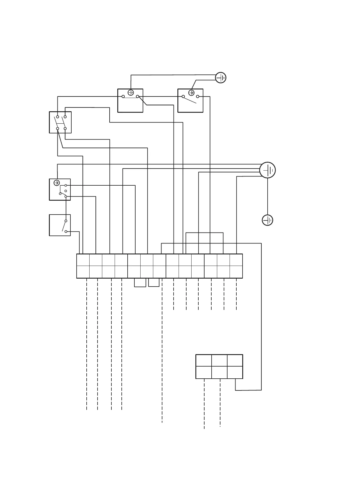
Figure 8-3: Vortex Pro External Module control panel wiring diagram
8.5 BOILER CONTROL PANEL WIRING DIAGRAMS
Section 8: Electrical