Page 40
Section 10: Commissioning
10.3 BURNER SETTINGS:
RDB3.2 BURNERS
FOR 46/58 AND 58/70 MODELS
With the burner removed from the boiler:
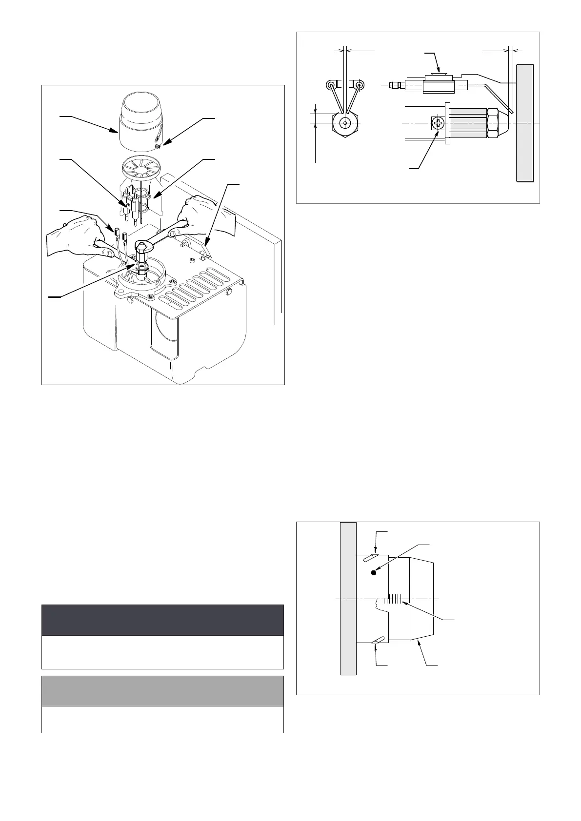
2
5
4
7
6
1
3
Figure 10-5: Riello RDB 3.2 burner head, diuser and nozzle
holder
1. Unscrew and remove the two screws holding the air intake
spigot to the top of the air inlet cover.
2. Remove and discard the air intake spigot and gasket.
3. Fit the slotted air intake (provided loose with the boiler) to the
top of the air intake cover and secure using one of the two
screws previously removed.
4. Remove the burner head. Refer to Figure 10-5. Loosen both
xing screws (3) and remove head from burner (2).
5. Check the nozzle is correct for the required boiler output.
Refer to Table 2-3 for the correct nozzle size and type for the
required boiler output.
6. If the nozzle needs to be replaced - Remove the diuser/
electrode assembly. Refer to Figure 10-5.
• Loosen the diuser clamp screw (7) and remove the
diuser/electrode assembly from the nozzle holder (6).
• Disconnect both ignition leads (4) from the electrodes.
7. Use a 16mm spanner to remove/re-t the nozzle, whilst
holding the nozzle holder using a 17mm spanner.
! CAUTION !
The use of an ill-tting spanner will damage the nozzle
and could lead to an incorrect ame pattern and poor
combustion.
! NOTE !
Ensure that the nozzle is securely tightened so that it does
not leak but DO NOT OVER TIGHTEN!
8. Reconnect ignition leads to electrodes.
9. Re-t the diuser/electrode assembly to the nozzle holder.
10. Refer to gure 10-5. Slide diuser (5) along the nozzle holder
(6) until hard against the stop and tighten diuser clamp
screw (7).
1
2
4mm
+
0
3mm
0
-
5.75mm
0.2
0.5
Figure 10-6: Ignition electrode settings
11. Check/adjust the electrode assembly to give the correct gap
(4mm) between the nozzle and electrodes. Refer to Figure
10-6.
• To adjust the electrode position:
- Loosen the electrode clamp screw.
- Slide the electrode assembly to give the correct gap
of 4mm.
- Tighten the electrode clamp screw.
12. Re-t the burner head. Refer to Figure 10-5.
• Locate the head xing screws in the countersunk slots in
the burner collar.
• Tighten the two screws (3) to secure the head (2) in
position on the burner.
13. Check the combustion head setting.
• The correct head setting depends on the required output
of the boiler. Refer to Table 2-3
• This should be set to ‘0’ in all cases except when the
58/70 is set to maximum (70kw) output.
• In this case the head is set to ‘4’ (i.e. on the 4th line).
Refer to Figure 10-7.
14. To adjust the head setting (if required):
• Loosen the two screws in the curved slots in outer ring
of the head (NOT the two head xing screws). Refer to
Figure 10-7.
• Rotate the end of the burner head until either ‘0’ or the
4th line, as required.
• Tighten the two screws to x the head in the required
position.
0
Shutter
Blast tube
Screw
Slotted ring
Screw
Figure 10-7: Riello RDB 3.2 Combustion Head Setting