Page 66
Appendix A2: Wilo-PARA 25-130/7-50/SC-6#GRA
A2.1.6 COMMISSIONING
After installation of the boiler, commission the pump by using the
following procedure:
Venting:
• Fill and vent system correctly. (Refer to Section 7)
• If the pump does not vent automatically use the pump vent
function.
• Press and hold the green operating button for 3 seconds and
release to start.
• The pump venting function will operate for 10 minutes, during
which the pump alternated between o and on to vent air
from the pump.
• Pump mode and pump curve LED rows ash in turn at 1
second intervals to indicate when this function is operating.
• To cancel, press and hold green operating button for 3
seconds.
• After 10 minutes the pump automatically reverts to the
previously set operating mode, e.g. constant speed -curve
III.
! NOTE !
After venting the LED display shows the previous pump
settings.
Set Control Mode
• Switch on power to the pump.
• The factory setting is Constant speed mode - pump curve III.
• This will be indicated by the control mode LED and pump
curve LED.
• Press the green operating button briey (approx. 1 second)
to change the pump setting.
• Continue to repeat pressing the button, using the following
sequence, until the required pump mode and pump curve are
set:
Operating button - Green (item 7, Figure A2-1)
• Press to select:
- Control mode
- Pump curve (within the control mode)
• Press and hold to:
- Activate the pump venting function (press for 3 seconds)
- Activate manual restart (press for 5 seconds)
- Lock/unlock control mode and pump curve (press for 8
seconds)
A2.1.5 OPERATING MODES
Wilo-Para 25-130/7-50/SC-6#GRA circulating pumps have three
possible operating modes:
• Variable dierential pressure (∆p-v) with three pre-dened
pump curves (I, II and III)
• Constant dierential pressure (∆p-c) with three pre-dened
pump curves (I, II and III)
• Constant speed with three pump speed settings (I, II and III)
Variable Dierential Pressure Mode (∆p-v)
Recommended for two-pipe heating systems with radiators to
reduce the ow noise at thermostatic valves.
In this mode the electronic control reduces the delivery head of
the pump to half in the case of decreasing volume ow in the
pipework. There are three pre-dened pump curves (I, II and III) to
choose from.
Constant Dierential Pressure Mode (∆p-c)
Recommended for underoor heating systems.
In this mode the electronic control maintains the set delivery head
irrespective of the volume ow from the pump. There are three
pre-dened pump curves (I, II and III) to choose from.
Constant Speed Mode
Recommended for systems with xed system resistance requiring
a constant volume ow from the pump.
This is the default setting of the pump and as such is
recommended by Grant for heating systems.
In this mode the pump speed is not automatically regulated (as
with the Variable or Constant dierential pressure modes) but
operates constantly at one of the three available speeds (I, II or
III)
! NOTE !
Factory default setting is Constant speed mode - pump
curve III.
Pump Venting Function
Activated by pressing and holding the green operating button for
3 seconds.
Automatically vents the pump. This function DOES NOT vent air
from the heating system.
Manual Restart (Unblocking) Function
Activated by pressing and holding the green operating button for
5 seconds.
Unblocks the pump when required, e.g. after a long idle period in
the summer.
Key Lock Function
Activated by pressing and holding the green operating button for
8 seconds.
Locks/unlocks the current pump settings set by the operating
button, preventing unwanted adjustment of the current pump
settings.
Factory Setting Function
Activated by pressing and holding the green operating button
whilst switching the pump o, and continuing to hold the button
down until all lights on the pump control panel are o.
When the pump is switched back on, it will operate at the original
factory settings.
Factory default setting is Constant speed mode - pump curve
III.
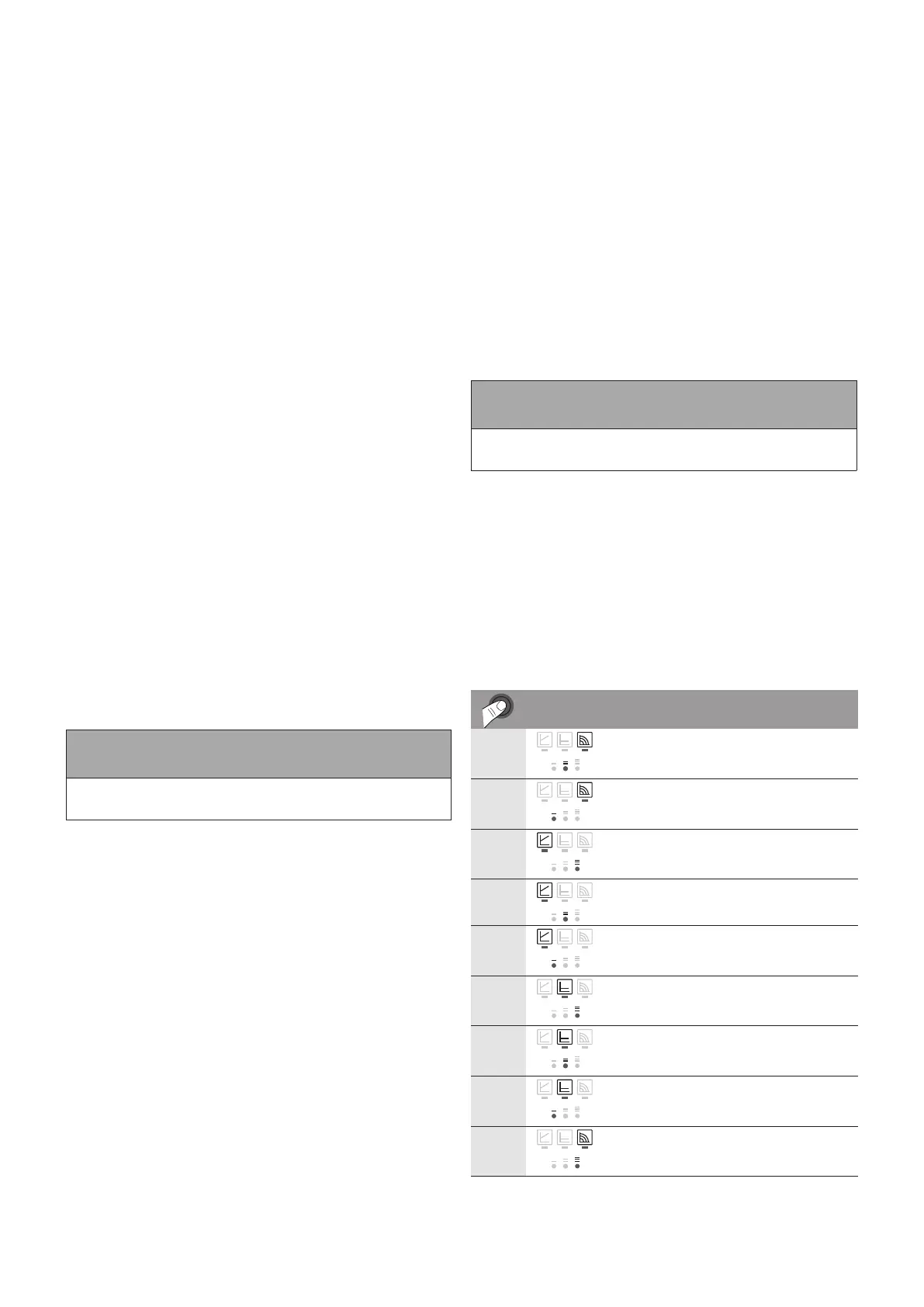
• Pressing the button for the 9th time returns to
the basic setting (constant speed / characteristic
curve III).
LED display Control mode Pump curve
1 Constant speed
II
2 Constant speed
I
3 Variable differential
pressure
Δp-v
III
4 Variable differential
pressure
Δp-v
II
5 Variable differential
pressure
Δp-v
I
6 Constant differential
pressure
Δp-c
III
7 Constant differential
pressure
Δp-c
II
8 Constant differential
pressure
Δp-c
I
9 Constant speed
III
Table A2-2: Setting pump control mode