27
PARKING BRAKE ADJUSTMENT
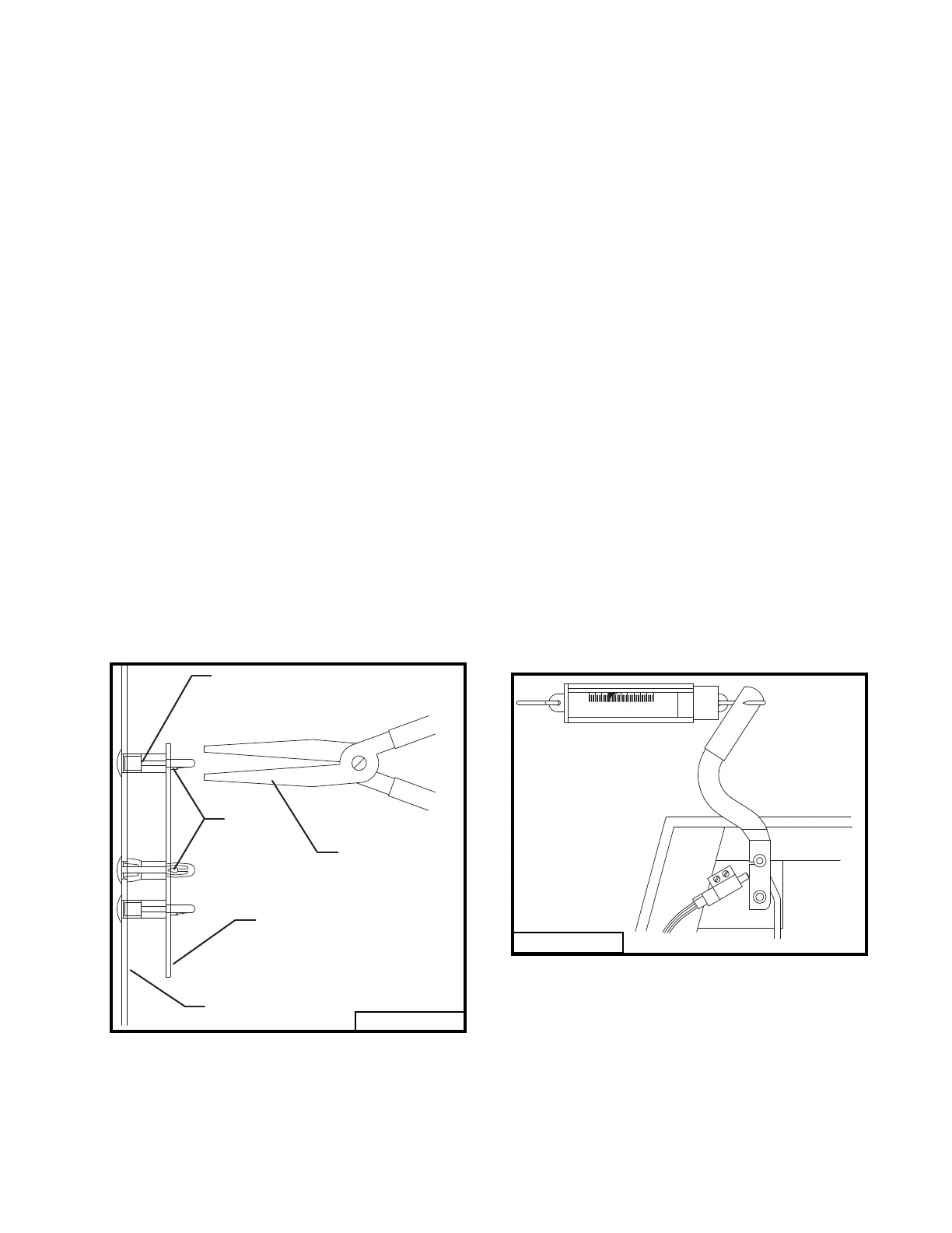
(Refer to Fig. 8 and illustration page 39.)
Adjust the right and left brake individually. Dis-
connect the right brake linkage rod (item 25).
Adjust the linkage pin (item 27) attached to
the left brake until it takes 14 lbs. of pull at
the top of the hand lever to apply the parking
brake. Adjustment of brake linkage arm (item
22) may also be required. Connect the right
brake linkage.
Disconnect the left brake linkage rod and ad-
just
the linkage pin attached to the right brake until
it takes 14 lbs. of pull at the top of the hand
lever to apply the parking brake. Connect the
left brake linkage.
With both brakes connected it should take 28
lbs. of pull at the top of the hand lever to apply
the parking brake. Adjust the brake linkage
arm (item 22) if necessary.
Be sure all cotter pins and jam nuts are se-
cured.
Fig. 8
97069A
0
10
20
30
40 50
Fig. 7
Keeper
Spacer - Circuit Board Support
Part no. 423690
Needle Nose
Pliers
Console Side
95040
Circuit Board
• If there is ground at both yellow wires on
the seat switch, check for ground at the
yellow wire on the parking brake switch. If
there is no ground, the wire between the
seat switch and the parking brake switch
is broken. If there is ground at the yellow
wire, check for ground at the white wire.
If there is no ground at the white wire, the
parking brake switch is defective and must
be replaced.
NOTE: These tests must be performed
with an accurate voltmeter. Do not use a
test light; the amperage in this circuit is
too low to properly light a test light. This
circuit is the ground side of relay A.
WIRING CIRCUIT BOARD
REMOVAL
Remove the circuit board from the console by
compressing the keeper in each of the three
circuit board support spacers with needle
nose pliers (refer to Fig. 7). Slide the board
past each keeper when it is compressed.