28
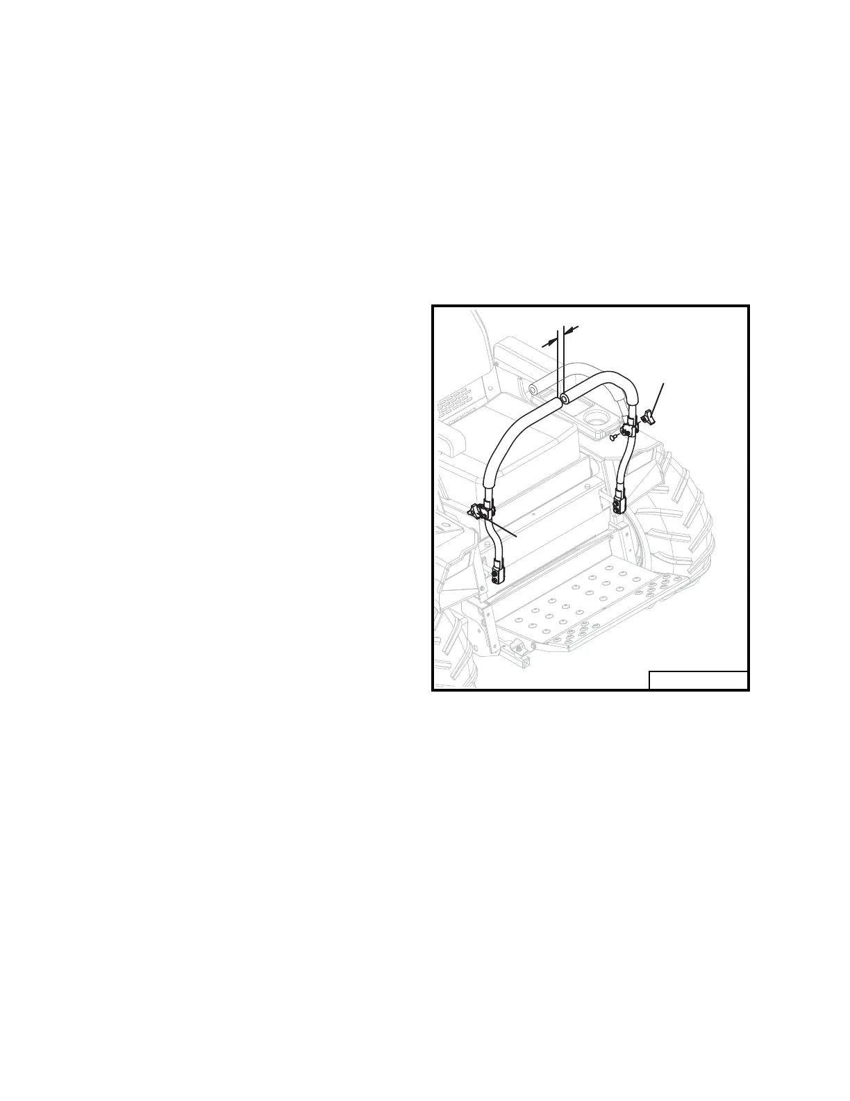
Fig. 9
IMPORTANT
CLUTCH REMOVAL /
REPLACEMENT
(Refer to page 42)
• Remove anti-rotation bracket (item 19).
•
Using a 15/16 inch wrench, rotate the idler
arm (item 23) with idler pulley (item 30)
away from belts and remove drive belts
(item 37).
•
Unplug wires from clutch and remove cen-
ter bolt (item 18). Slide clutch off engine
crankshaft.
•
Reverse order to install new clutch.
•
Torque clutch bolt to 50 ft lbs. Run clutch
15 minutes, then torque to 50 ft lbs again.
CLUTCH / BRAKE BURNISHING
A new clutch, or one that has not
been used for three months, will
require burnishing to dress drive
surfaces. The clutch could fail if
you do not accomplish the follow-
ing procedure.
Place tractor in neutral, start engine and run
at fast idle. Turn clutch switch on 30 seconds
and off 30 seconds, fi ve times at half-throttle
and repeat fi ve times at full throttle. The time
interval allows the clutch surface to cool.
STEERING LEVER ADJUSTMENT
To adjust steering levers, loosen 3 prong
thumb nuts that secure the upper levers to
the lower. This allows the upper levers to
be moved backward (refer to Fig. 9). Set
levers to a comfortable position for the opera-
tor. Hold levers in position and tighten thumb
nuts. The levers must line up when in neutral
position and maintain a minimum of one inch
of clearance between end of levers.
1"
10132A
3 Prong
Thumb Nut
3 Prong
Thumb Nut
Rev. 06-16