109
Programming example: delta and fl ying wing
same direction and provide an elevator effect when an
elevator command is given. The procedure starts by
selecting the …
»wing mixer« (pages 72 … 76)
ail
ail
diff aile.
rudd
flaps
+
0%
brak
brak
brak
elev
flap
aile
elev
elev
flap
flap
aile
elev
flap
diff–red
aile
SEL
+
0%
+
0%
+
0%
+
+
0%
+
+
+
+
+
0%
+
0%
diff. flaps
50%
50%
66%
77%
77%
… menu where you set values other than zero for the
fi
xed-wing mixers “Elevator ¼ N.N.*”.
(The following settings are model-specifi c, and you
must check carefully that they work correctly on
your model before accepting them.)
With this set-up the tailless model is considered to be
a
“normal” four-fl ap wing (two ailerons and two fl aps),
and therefore has all the options associated with this
wing type. The method involves the “Elevator ¼ N.N.*”
mixers, which were originally intended only for pitch trim
compensation and non-standard applications. In this
case they are “abused” by setting higher values than
normal, in order to transfer the elevator signal to the
control surfaces of the tailless model.
However, none of the fi xed-wing mixers includes the
»wing mixer« (pages 72 … 76)
+
0%
SEL
+
0%
+
0%
+
0%
ail
diff aile.
rudd
brak
elev
diff–red
… menu affect the elevator (up / down) function of the
tw
o elevon (combined aileron / elevator) servos, as well
as the fl ap / elevator servos.
Notes:
The fl ap mixers and fl ap differential only appear in •
the list if you have also entered “2 fl ” in the “aile / fl ap”
line at the “Delta / Flying wing” model type; see illus-
tration on the right.
In principle the same applies to the “Brake • ¼ N.N.*”
mixers. These are also suppressed if you have decid-
ed on “Throttle min forward / back” in the “motor on
C1” line of the »base sett.« menu.
Even if you have selected “2aile 2fl ”, the (digital) el-•
evator and aileron trims only affect aileron / elevator.
If you wish to circumvent this it is simpler to program
your model as described in the following section.
Programming a model delta using the “normal” tail
setting
Alternatively, if you select the “normal” tail type in the
»base sett.« menu, and connect the servos to the
receiver as shown in the lower of the two receiver socket
sequence diagrams on the previous page, then the
aileron function of the two elevon servos will work cor-
rectly, but not the elevator function.
In the “normal” tail type you have to force the two
aileron servos and the two fl ap servos to move in the
digital trim of the elevator stick – so an alternative has to
be found.
Start by switching to the …
»contr set.« (page 58)
I5
I6
I7
+
trv
15%
15%
100%
100%
SEL
SYM
ASY
ctrl6
empty
++
++
ctrl6
15%
15%
++
… menu and assign the same transmitter control to the
inputs 5 and (if required) 6, e
. g. the INC / DEC buttons,
CTRL 6; this is used because its positions are stored
separately for each fl ight phase. Now move to the
“Travel” column and reduce the travel of the transmitter
control for these two inputs symmetrically to around
50%, or even less, because: the lower this value, the
fi ner the trim control.
However, if you prefer to use the normal elevator trim
lever, set the “Elevator ¼ N.N.*” mixers to 0%, and
instead set up free linear mixers to do the job.
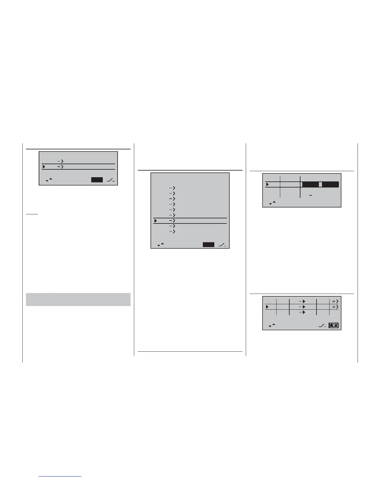
This is done by calling up the ...
»free mixer« (pages 89 … 93)
SEL
SEL
typ fro
to
M1
M2
M3
el
5
????
tr
el
6
tr
… menu and setting up one linear mixer “tr el ¼ 5”
(for
the simplest case), and possibly “tr el ¼ 6”. Move to
the graphic page of this menu to set the required mixer
ratios. Check the settings, and above all the direction of
* N.N. = Nomen Nominandum (name to be stated)