8
Description of radio control system
of changing the stick mode (modes 1 - 4, e. g. throttle
r
ight / throttle left). When you change modes, all the
affected settings are switched at the same time.
Graphical servo display provides a straightforward •
overview of the servo set-up, and a swift method of
checking servo travels
Receiver output swap•
Fixed-wing menu for: 1 AIL, 2 AIL, 2 AIL + 2 FLAP, •
V-tail, delta / fl ying wing, two elevator servos
Fixed-wing mixer: diff aile, diff.fl aps, ail • ¼ rudd, ail
¼ fl aps, brake ¼ elev, brake ¼ fl ap, brake ¼ aile,
elev ¼ fl ap, elev ¼ aile, fl ap ¼ elev, fl ap ¼ aile
and diff. reduction
Heli menu: 1-point, 2-point, 3-point and 4-point link-•
ages (1 servo, 2 servo, 3sv(2roll), 3sv(2nick (pitch-
axis)), 4 SV (90°))
Servo travel adjustment ±150% for all servo chan-•
nels, variable for each end-point separately (Single
Side Servo Throw)
Sub-trim for fi ne-tuning the neutral position of all •
servos
Servo reverse, programmable for all servos•
EXPO / DUAL-RATE system, separately variable, can •
be switched in-fl ight
Mixer functions:•
Aileron differential mixer, butterfl y mixer, fl aperon
mixer and three freely programmable mixers
Convenient swashplate programs for model helicop-•
ters
Programmable Fail-Safe function in receiver with •
“hold-mode” and “move to preset position” function,
variable separately for each servo channel
Stopwatch / count-down timer with alarm function•
Model memory copy function•
Integral DSC socket for use with fl ight simulators and •
Trainer systems
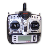
mx-16 COMPUTER SYSTEM
Eight-channel radio control system exploiting Graupner | iFS technology (intelligent frequency select)

 Loading...


