155
Pre-set modulation
The mx-24s differentiates between six different types
of modulation:
1. PCM20: System resolution of 512 steps per chan-
nel, for “mc” or “DS mc” type PCM receivers.
2. SPCM20: Super PCM modulation with high sys-
tem resolution of 1024 steps per control function,
for “smc” type receivers and the “R330”.
3. APCM24: Super PCM modulation with high sys-
tem resolution of 1024 steps per control function,
for “amc” type receivers, for up to twelve servos.
4. PPM10: Fast PPM transmission mode for Pico re-
ceivers with up to fi ve servos, as used in RC cars,
slow-fl y models, small helicopters, etc..
5. PPM18: Most widely used transmission mode (FM
or FMsss) for all other GRAUPNER/JR PPM-FM
receivers.
6. PPM24: PPM multi-servo transmission mode for
simultaneous operation of twelve servos; for “DS
24 FM S” receiver.
Pressing CLEAR switches to the default “SPCM20”
modulation type.
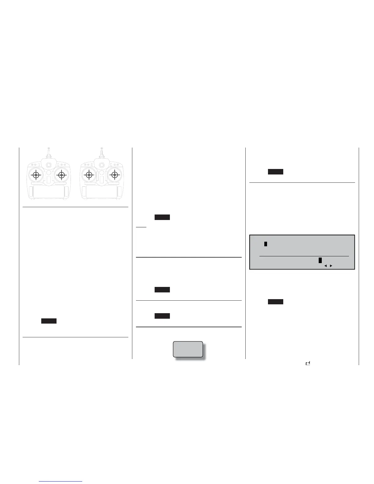
Pre-set min. pitch (model helicopters only)
At this point you can defi ne the operating direction
of the throttle / collective pitch stick in the Helicopter
programs; it should be selected to suit your preferred
method of controlling your models. This is very impor-
tant, as the function of all the other options in the he-
licopter program depends upon it, in so far as they af-
fect the throttle and collective pitch functions, i. e. the
throttle curve, idle trim, Channel 1 tail rotor mixer
etc.
Key to settings:
“forwrd”: minimum collective pitch setting when the
collective pitch stick (C1) is forward (away
from you)
“back”: minimum collective pitch setting when the
collective pitch stick (C1) is back (towards
you).
Pressing CLEAR resets to “forward”.
Note:
The direction of operation of the C1 stick for the fi xed-
wing program can be reversed individually in the
»Channel 1 curve« menu (see page 92), or – prefe-
rably – in the »Model type« menu.
Display light
In this line you can determine how long the screen
backlighting stays on when the transmitter is switched
on, or after you press a button or operate the rotary
control.
The options are 30, 60, 120 seconds or “unlimited”.
Pressing CLEAR switches the setting to “unlimited”.
Power-on beep
In this line you can switch the transmitter’s power-on
beep on (“yes”) or off (“no”).
Pressing CLEAR switches to “yes”.
Battery warning
In this line you can set the voltage threshold for the
following warning display …
155
Program description:
Global functions
… within the range 9.3 to 11 V in increments of 0.1
Volts. Please don’t be tempted to set a very low value
here, as you need plenty of time to land your model
safely if the battery warning is triggered.
Pressing CLEAR switches to “9.3 V”.
Own phase name 1 … 10
You can enter up to ten of your own phase names,
each with a maximum of seven characters, drawn
from a character list. These names are then availab-
le in addition to the default phase names in all model
memories.
We recommend that you start with the “User’s phase
name 1” line when entering your own phase names.
A brief press on the rotary control takes you to the
character table.
Own phase name
A
!“#$%&´( )*+,-./0123456789:;<=>?
@ABCDEFGHIJKLMNOPQRSTUVWXYZ[¥]^_
`abcdefghijklmnopqrstuvwxyz{}~
c
N
ÇüéâäàåçêëèïîìÄÅÉæÆôöòûùÿÖÜ
1< >
--
Use the rotary control to select the desired character
in the highlighted character fi eld. A brief press on the
rotary control (or turning it whilst pressed in) switches
to the next position, at which you can select the ap-
propriate character.
Pressing CLEAR inserts a space character at that
point.
Hold the rotary control pressed in to move to each
character within the name. The next space is indica-
ted by a double arrow <--> in the bottom line.
Batt must
be re-
charged!!
min. Pitch
Roll
Roll
max. Pitch
Pitch-axis
Pitch-axis
Tail rotor
Tail rotor
Pitch-axis
Pitch-axis
Roll
Roll
min. Pitch
max. Pitch
Tail rotor
Tail rotor
»MODE 3«
(Pitch right)
»MODE 4«
(Pitch left)