74
Column 3 “cent.”
The facility to offset the servo travel centre is intended
for adjusting servos whose centre setting is not stan-
dard (servo centre point at 1.5 ms), and also for slight
adjustments, e. g. when adjusting the neutral point of
a model’s control surfaces.
The neutral position can be shifted within the range
-125% to +125% of normal servo travel within the ma-
ximum servo travel of +/-150%, regardless of the trim
lever position and any mixers you have set up. The
centre setting affects the associated servo directly, re-
gardless of all other trim and mixer settings.
Pressing CLEAR resets the value to “0%”.
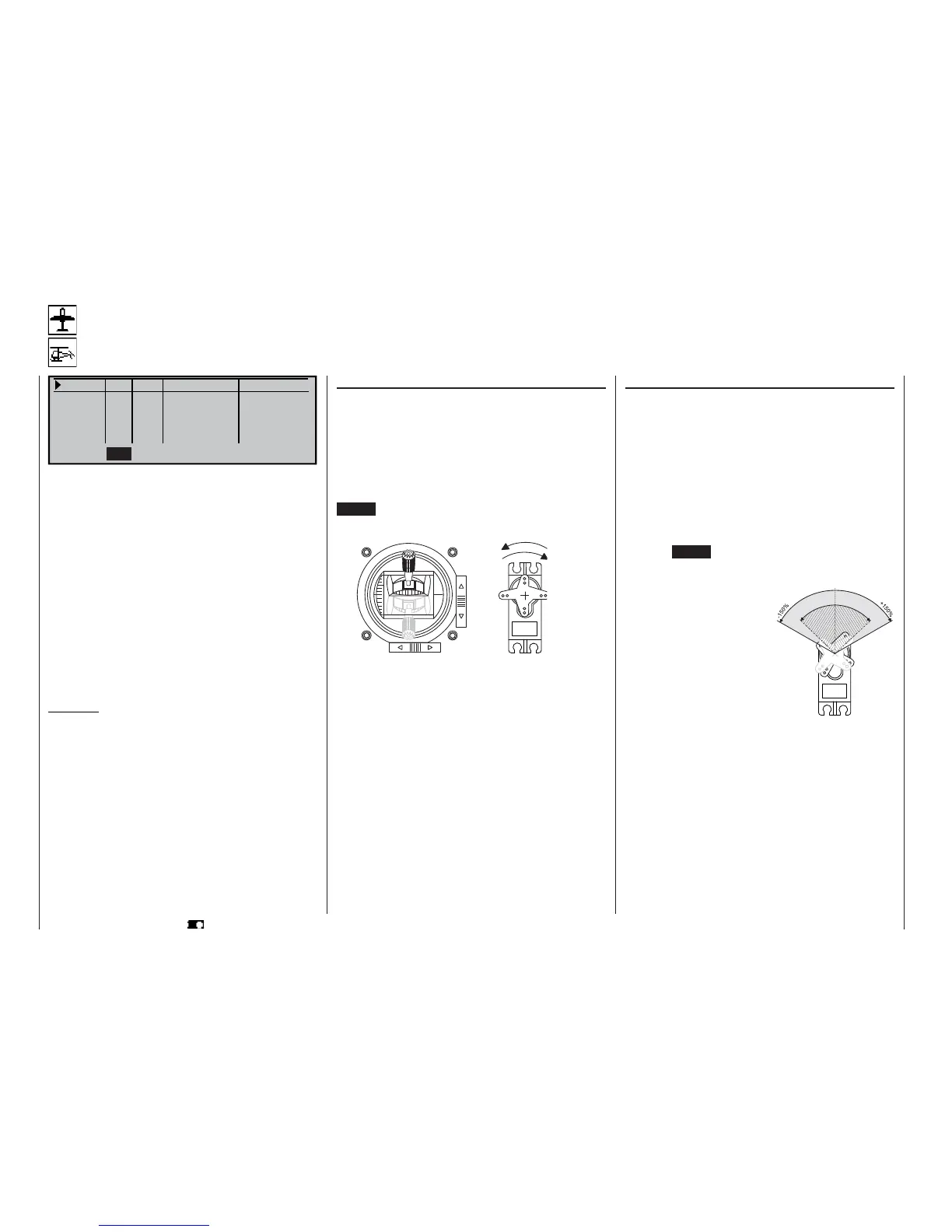
Column 2 “Rev”
The direction of servo rotation can be adjusted to suit
the actual installation in your model. This means that
you don’t need to concern yourself with servo direc-
tions when installing the mechanical linkages in the
model, as you can reverse them if necessary. The di-
rection of rotation is indicated by the symbols “=>”
and “<=”. Be sure to set the direction of servo rotation
BEFORE you adjust the remaining options!
CLEAR resets the direction of rotation to “=>”
Servo adjustment
Setting servo direction, centre, travel and limit
Servo 1 => 0% 100% 100% 150% 150%
Servo 2 => 0% 100% 100% 150% 150%
Servo 3 => 0% 100% 100% 150% 150%
Servo 4 => 0% 100% 100% 150% 150%
Rev
SEL SYM ASY SYM
ASY
cent. – travel + – limit +
SEL
In this menu you can adjust parameters which only
affect the servo connected to a particular receiver
output, namely the direction of servo rotation, neutral
point, servo travel and (if required) travel limit.
Basic procedure:
1. Hold the rotary control pressed in and select the
appropriate servo (1 to 12).
2. Turn the rotary control to select SEL, SYM or ASY
in the bottom line, prior to making the adjustments
required.
3. Press the rotary control: the corresponding input
fi eld is highlighted (dark background).
4. Set the appropriate value using the rotary control.
5. Finally press the rotary control again to end the in-
put process.
Important:
The numbers in the servo designations refer to the
receiver output socket to which a particular servo is
connected. These numbers do not necessarily coinci-
de with the numbering of the transmitter control func-
tion inputs; indeed any agreement would be pure-
ly accidental. The sophisticated programs of the mx-
24s mean that the numbers are unlikely to be the
same in any case. For example, changing the stick
mode does not affect the numbering (i. e. receiver so-
cket sequence) of the servos.
As a basic rule, always start with the servo setting in
the left-hand column!
Program description: Basic settings
Servo centre offset
S
e
r
v
o
t
r
a
v
e
l
-
1
2
5
%
C
e
n
t
r
e
a
d
j
u
s
t
m
e
n
t
+
1
2
5
%
normal
reversed
reversed
normal