75
Column 5 “- limit +”
The servo travels generated by superimposed mixers
are cumulative, and at the extremes these can ex-
ceed the normal permissible limits. This also applies
when other parameters are adjusted, such as signi-
fi cant centre offset plus enlarged travel. All GRAUP-
NER/JR servos have a reserve of an additional 50%
beyond normal travel, so the transmitter normally li-
mits servo travel to 150% to avoid mechanical dama-
ge due to the servos striking their end-stops.
In some cases it may be advisable to set the limiter
to restrict servo travel to a lower value, for example, if
there are mechanical limits in the linkage; this should
only be carried out if the control travels normally re-
quired in fl ight will not be reduced unnecessarily by
restricting servo travel in this way.
Example:
A servo may be controlled by two transmitter cont-
rols through different mixers. For model-specifi c re-
asons a maximum servo travel of no more than 100%
is possible, because – for example – the rudder would
foul the elevator at more than 100% travel. As long as
only one transmitter control is used, this presents no
problem. Diffi culties only arise if the signals add up to
more than 100% when both transmitter controls (e. g.
aileron and rudder) are moved simultaneously. In this
case the strain on the mechanical linkages could be
severe, perhaps with catastrophic results.
To avoid this danger it is important to limit the servo
travel individually. In our example – the rudder – this
would be a value just below 100%, as we have estab-
lished that it fouls the elevator at 100% travel.
For symmetrical travel limiting, select the SYM fi eld
and set a value within the range 0 and +150% of nor-
mal. For an asymmetrical setting select the ASY fi eld,
then press the rotary control briefl y and use the rota-
ry control again to set the travel limit values in each
highlighted fi eld. For an asymmetrical setting move
the associated transmitter control to each end-point in
turn; the highlighted fi eld then switches between the
negative and positive directions.
(CLEAR = 150%.)
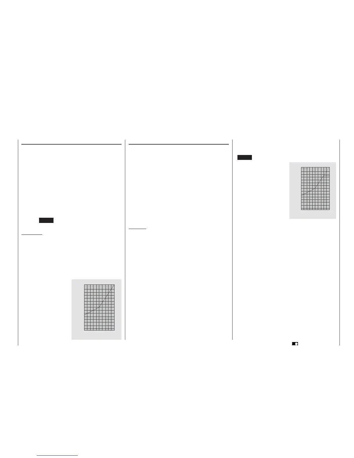
The graph shows the servo
travel limited to 90%, with a
travel setting of +150%.
Program description: Basic settings
Column 4 “- travel +”
In this column you can adjust servo travel symmetri-
cally or asymmetrically (different each side of neutral).
The adjustment range is 0 … +150% of normal ser-
vo travel. The reference point for the set values is the
setting in the “Centre” column.
To set a “symmetrical” travel, i. e. to adjust travel
equally on both sides of neutral, select SYM; se-
lect ASY to set asymmetrical travel. In the latter case
move the associated transmitter control (stick, INC
/ DEC button, side-mounted proportional control, or
switch) to the appropriate end-point; when you press
the rotary control the highlighted servo travel fi eld
switches between the left fi eld (negative direction)
and the right fi eld (positive direction).
Pressing CLEAR resets the changed parameter to
100%.
Important:
In contrast to the »Transmitter control adjust«
menu this value affects the servo directly, regardless
of how the control signal for this servo is generated,
i. e. either directly by a stick channel, or by means of
any type of mixer function.
0
2 0
4 0
6 0
8 0
1 0 0
1 5 0
%
0 2 0 4 0 6 0 8 0 1 0 0 %
Servo travel
Transmitter control travelt
The graph alongside shows an
example of asymmetrical servo
travel, with a travel setting of -
50% and +150%.
0
2 0
4 0
6 0
8 0
1 0 0
1 5 0
%
0 2 0 4 0 6 0 8 0 1 0 0 %
Transmitter control travel
Servo travel