95
Program description:
Switches
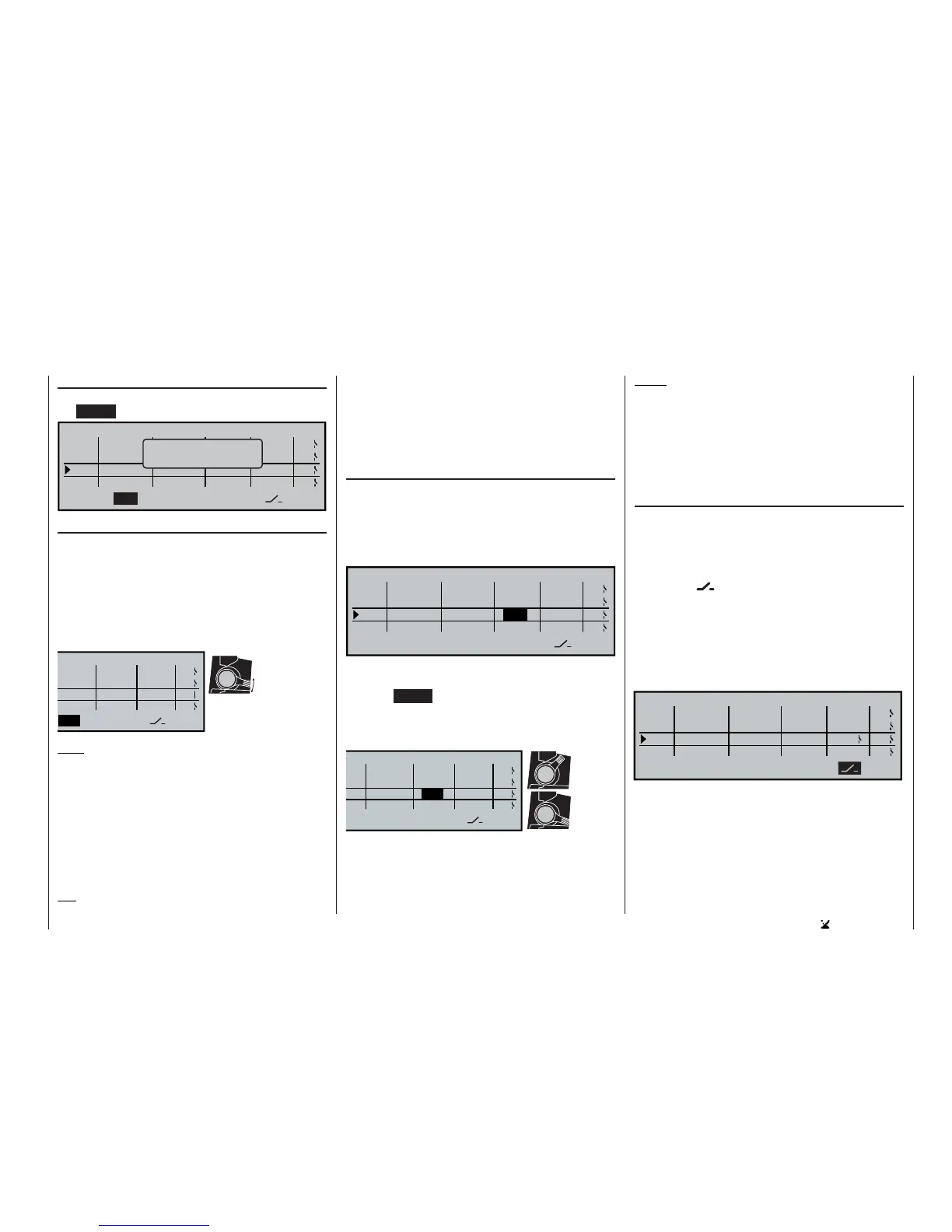
Resetting a control switch to “free”
If you wish to reset a control switch to “free”, press
the CLEAR button at this display:
SEL
–75%
=>
+75%
=>
0%
0%
=>
=>
STO
SEL
Cnt.
1
1
9
CONTROL SWITCH
G1 Cnt.
G2
G3
G4
G1
G2
G3
G4
Cnt.
free
Move desired
control adj.
Defi ning the switching point
Move the highlighted fi eld to the STO column (STO =
store, save).
Move the selected transmitter control to the position
where the switching point is to be located, i. e. the ON
/ OFF switch point, then give the rotary control a brief
press. The current position is displayed: in our examp-
le this is “+85%”. The switching point can be altered at
any time with another press on the rotary control.
Note:
It is not a good idea to place a switching point at the
end of a transmitter control’s travel, as there can then
be no guarantee that the function will be switched re-
liably.
In this example the control switch “G3” is open as
long as control 9 (the throttle limiter for a helicopter) is
below the +85% control travel point. It closes as soon
as the switching point is exceeded, i. e. in the range
between +85% and the top end-point.
Tip:
If you now assign, say, a stopwatch to this G3 switch
in the »Timers (general)« menu, the timer will start
running when you move the (throttle limit) slider to the
forward end-point, and vice versa. This assignment
may well be of practical use with model helicopters in
order to record the motor run time.
Determining the direction of operation of the con-
trol switch
In the 4th column the direction of operation of the
control switch can be reversed using the rotary con-
trol; it is shown in a highlighted fi eld. You need to se-
lect the right-hand SEL fi eld using the rotary control
before you reverse the direction. Press the rotary con-
trol briefl y:
SEL
–75%
+75%
=>
+85%
0%
=>
=>
SEL
STO
<=
free
1
1
9
Cnt.
Cnt.
Cnt.
CONTROL SWITCH
G1
G2
G3
G4
G1
G2
G3
G4
Turn the rotary control to select the desired direction
of switching in the highlighted fi eld.
Pressing CLEAR resets the direction of switching to
“=>”.
The current status of the control switch is indicated in
the extreme right-hand column by the switch symbol.
In the example shown here, with the switching point
reversed, the control switch “G3” is closed (ON) when
the transmitter control is below +85% travel; it opens
as soon as the switching point is exceeded, i. e. in the
range between +85% and the upper end-point.
SEL
–75%
=>
+75%
=>
+85%
0%
=>
=>
STO
OL SWITCH
G1
G2
G3
G4
SEL
–75%
+75%
=>
+85%
0%
=>
=>
NTROL SWITCH
G1
G2
G3
G4
“G3”
open
“G3”
closed
Defi ning the switching point:
Move the transmitter control to the ap-
propriate position and press the rotary
control briefl y.
Notes:
• If you assign a control switch, e. g. G3, to multiple
functions, it is important to remember that the swit-
ching direction set here applies to all G3 switches.
• The switched state can also be reversed by rever-
sing the transmitter control in the »Transmitter
control adjust« menu.
Combining a control switch with one of the swit-
ches SW 1 … 10
Any control switch can be over-ridden by another
switch, so that, for example, in particular fl ight situati-
ons the function can be switched independently of the
transmitter control position (and therefore of the cont-
rol switch).
Move to the
fi eld in the 5th column. In the simp-
lest case select one of the switches SW 1 … 10, as
described on page 32 in the section entitled “Assi-
gning transmitter controls and switches”. The num-
ber of this switch, e. g. No. 2, appears on the screen
in the second column from the right, together with a
switch symbol which indicates the momentary state of
the switch (on / off):
SEL
–75%
+75%
=>
+85%
0%
=>
=>
SEL
STO
<=
2
Cnt.
free
Cnt.
Cnt.
1
1
9
CONTROL SWITCH
G1
G2
G3
G4
G1
G2
G3
G4
As long as this switch is open, the control switch “G3”
in the right-hand column is active, i. e. it switches at
the set switching point. If the switch is closed, the
control switch remains constantly closed, regardless
of the position of the transmitter control and the direc-
tion of switching: