96
Program description:
Switches
SEL
–75%
+75%
=>
+85%
0%
=>
=>
SEL
STO
<=
2
1
1
9
CONTROL SWITCH
G1 Cnt.
G2
G3
G4
G1
G2
G3
G4
Cnt.
free
Cnt.
Combining two control switches
For more complex applications it may also be neces-
sary to over-ride this control switch with a second
control switch.
Example:
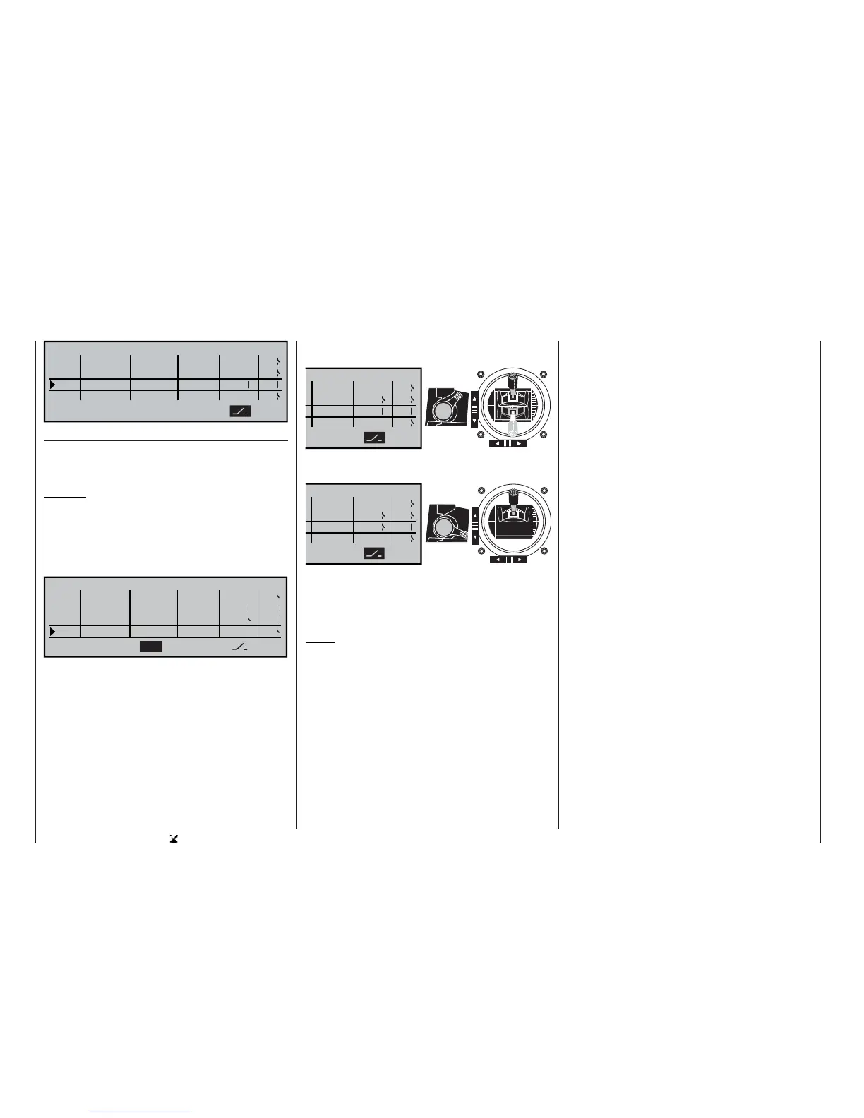
Control function 3 (= CONTROL 3) has been assig-
ned to the control switch “G4”. The switching point is
at its centre point, i. e. at 0%. Assign one of the two
side-mounted proportional controls, e. g. the left-hand
control 10, to the control switch “G5”. The switching
point of this transmitter control might be at +50%.
SEL
=>
+75%
+85%
0%
=>
=>
SEL
+50%
G5
STO
1
9
3
10
<=
2
Cnt.
CONTROL SWITCH
G2 Cnt.
G3
G4
G5
G2
G3
G4
G5
Cnt.
Cnt.
Assuming that the switching directions are as sta-
ted in the 4th column of the screen, the control switch
“G4” is now closed as long as the stick (Cnt. 3) and
/ or “transmitter control 10” are beyond the switching
point.
“G5” closed
“G4” always closed, re-
gardless of the position
of transmitter control 3
“G5” open
“G4” closed when transmit-
ter control 3 is “forward”
SEL
=>
=>
=>
<=
2
G5
G5
SWITCH
G2
G3
G4
SEL
=>
=>
=>
G5
G5
<=
2
SWITCH
G2
G3
G4
This comprehensive range of switching facilities offers
plenty of scope for special applications in the whole
fi eld of model fl ying.
Notes:
• The switching directions vary according to the op-
tion you have selected at “Throttle min. back / for-
ward” and / or “Collective pitch min. back / for-
ward”, as set in the »Model type« and »Helicop-
ter type« menus.
• If you are using a three-position switch (CON-
TROL 7 or 8) to operate the control switch, you
must fi rst program the switching point by means of
a proportional control, e. g. using one of the side-
mounted proportional controls or one of the INC /
DEC buttons:
Start by assigning the “substitute” proportional
control in the 2nd column, and set the switching
point in such a way that the one position of the
three-position switch will reliably exceed that va-
lue, e. g. -10% or +10%. If you neglect this, the
switching function will not be reliable, as the cont-
rol switch is only triggered when the signal signifi -
cantly exceeds or falls below the set value. The fi -
nal stage is to reverse the control assignment, and
re-assign the three-position switch which you actu-
ally intend to use.
Transmitter control positions, and control switch posi-
tions: