97
Program description:
Switches
Logical switch
Combining switches
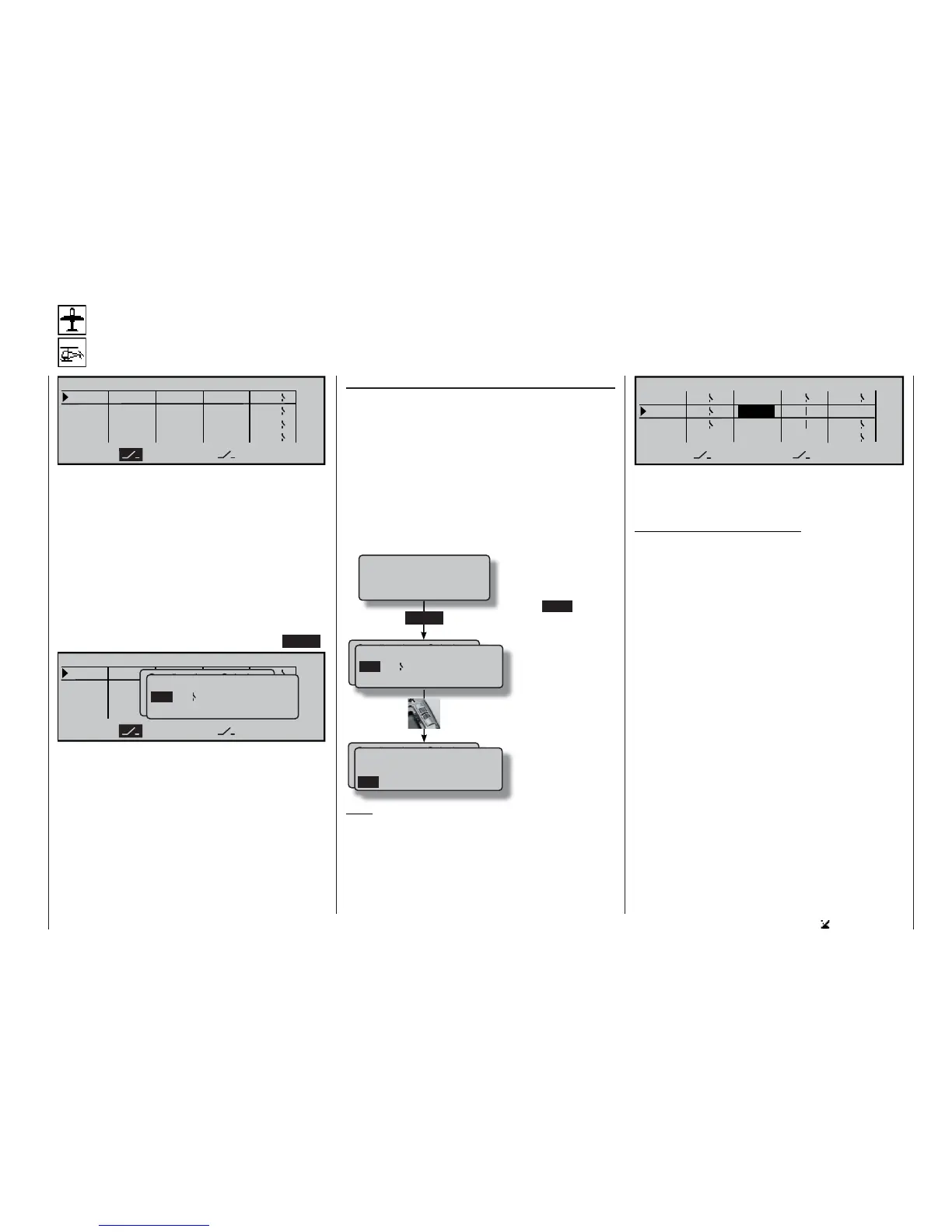
LOGICAL SWITCHES
L1
L2
L2
L3
L4
SEL
AND
AND
AND
L1
L3
L4
AND
This function provides a means of linking two swit-
ches, control switches and / or logical switches, or
any combination of them, in an “AND” or “OR” circuit.
In total the software allows eight logical switches “L1
… L8” to be programmed.
The result of such a logical switch function – explai-
ned later in this section – can be used as a further
switching function. The switches required to set up a
logical link of this type are assigned in the usual way
using the two switch symbol fi elds, i. e. by moving the
appropriate switch or transmitter control from the OFF
to the ON position, and by selecting an expanded
switch using the rotary control after pressing ENTER:
L1
L2
L2
L3
L4
SEL
UND
UND
UND
L1
L3
L4
UND
Gewünschten Schalter
oder Geber betätigen
(erw. Schalt.: ENTER)
Logical / fixed switch
FX L1 L2
FXI
L3 L4
L5 L6 L7 L8 L1i L2i
LOGICAL SWITCHES
Possible applications for such links:
• Several functions which are normally switched inde-
pendently of each other are to be grouped together
so that they can be brought to a defi ned base set-
ting when the user operates an “emergency switch”.
• The operation of a particular function is required to
switch another function, e. g. switching to the “nor-
mal” fl ight phase when a braking system is deploy-
ed; see example on page 178.
• Defi ning linked situations in which a power-on
warning is triggered; see the »Base setup mo-
del« menu.
“AND” / “OR”
The “AND” or “OR” link is selected using the rotary
control after activating the SEL fi eld.
“AND” function: a logical switch is only closed if
both switches are closed.
“OR” function: a logical switch is closed if either
of the two assigned switches is
closed.
To enable these logical switches to be used in
practice, the switch select list is expanded to inclu-
de these special switches in those menus where swit-
ches can be selected:
Note:
The screen-shot printed below clearly shows the dif-
ference between AND and OR switches by the switch
positions:
Gewünschten Schalter
oder Geber betätigen
(erw. Schalt.: ENTER)
Logical / fixed switch
FX L1 L2
FXI
L3 L4
L5 L6 L7 L8 L1i L2i
ENTER
Gewünschten Schalter
oder Geber betätigen
(erw. Schalt.: ENTER)
FXI
L5 L6 L7 L8 L1i L2i
L3i L4i L5i L6i L7i L8i
Logical / fixed switch
Press ENTER if you
wish to move to the ex-
panded switches.
Now use the rotary con-
trol to search for the
desired fi xed switch “F”
or logical switch “L”. In
addition to the logical
switches “L1 to L8” the
list also includes the in-
verted switches “L1i to
L8i”.
L1
L2
4
L2I
L3
L1
L4
SEL
AND
1
3
OR
AND
AND
2L1
L2 L3
L4
LOGICAL SWITCHES
“L3” is only closed if both switches “L1” and “L2” are
closed. This means: the two switches 1 and 2 must be
closed, and at the same time either switch 3 or 4.
Note regarding inverted switches:
If you select an inverted switch at the switch assign-
ment stage – e. g. “L1i” instead of “L1” – then the di-
rection of switching is simply reversed, i. e. if a parti-
cular switch is required to activate, say, a mixer when
switched on, then the same switch with the suffi x “i” (=
inverted) will activate this function when it is switched
off. More complex applications can be addressed, for
example, if you set up one and the same switch to
turn one function on, but at the same time to turn a
second function off, and vice versa. Very sophistica-
ted switching arrangements can be produced in con-
junction with the logical switches.
Move desired switch
to ON position
(ext. switch: ENTER)