98
How do I program a fl ight phase?
The meaning of fl ight phase programming
Program description: Flight phases
General notes on fl ight phase programming
Often there are particular stages in a fl ight where you
always need to use particular settings: perhaps diffe-
rent fl ap positions for launch and landing with a fi xed-
wing aircraft, or different collective pitch and throttle
settings for hover and auto-rotation with a helicopter.
The
mx-24s enables you to store these different set-
tings in separate fl ight phases, and call them up auto-
matically using a switch or even a control switch.
Another very useful application for fl ight phases is the
fl ight-testing procedure with a new model: you can set
up different fl ight phases containing alternative con-
trol surface settings, then switch between them in
fl ight in order to establish the most effective set-up for
the model in question.
The basic programming procedure is carried out
in three stages
1. First you have to set up the different fl ight pha-
ses, i. e. you assign names to phases 1 … max.
8, which are then included in all the phase-speci-
fi c menus and in the basic screen display. It is also
possible to program a time frame for a “soft” transi-
tion into the next phase, so that the model moves
smoothly from one phase to the next, rather than
abruptly.
For fi xed-wing model aircraft these settings are
programmed in the »Phase settings« menu. In
the Helicopter program you start in the »Base se-
tup model« menu if you wish to set up an auto-
rotation facility, otherwise you also start program-
ming in the »Phase settings« menu.
2. In the second stage you set up the required “pha-
se switches” in the »Phase assignment« menu.
3. Once these preliminary steps have been comple-
ted, you can move to the specifi c phase menus
and start programming the settings for the indivi-
dual fl ight phases, as shown in the tables below.
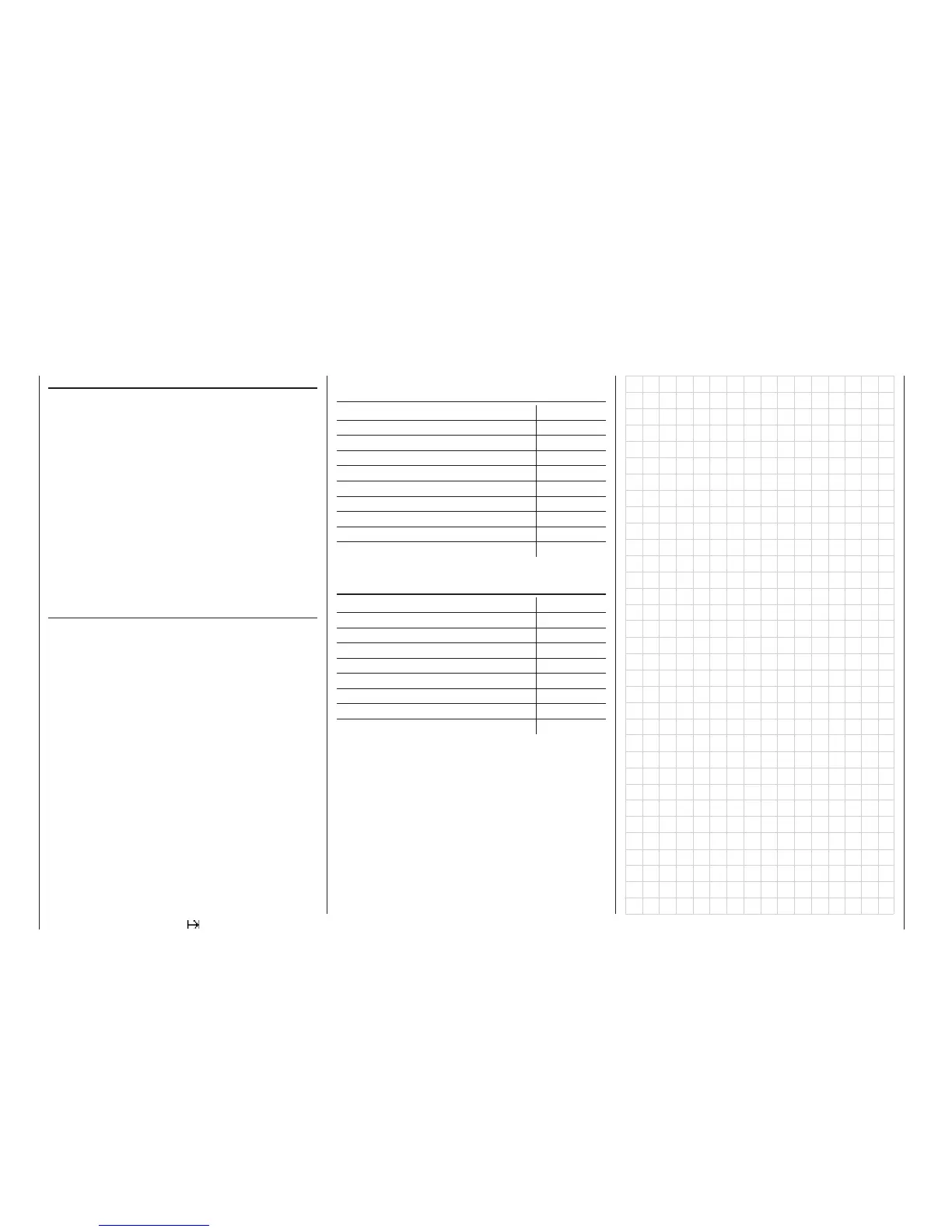
List of fi xed-wing menus which are variable sepa-
rately for each fl ight phase:
Menu page
»Control switch« (Eingang 5 … 8) 78
»Dual Rate / Expo« 86
»Channel 1 curve« 90
»Phase settings« 100
»Phase assignment« 104
»Phase trim F3B« 105
»Non-delayed channels« 105
»Wing mixers« 110
»MIX active in phase« 142
List of helicopter menus which are variable sepa-
rately for each fl ight phase:
Menu page
»Control switch« (Eingang 5 … 8) 80
»Dual Rate / Expo« 88
»Channel 1 curve« 92
»Phase settings« 102
»Phase assignment« 104
»Non-delayed channels« 105
»Helicopter mixer« 122
»MIX active in phase« 142
All the other menus are model-specifi c, i. e. they can-
not be programmed separately for different fl ight pha-
ses. All changes you make in the other menus app-
ly equally to all fl ight phases for that specifi c model. In
some cases you may wish to remove the non-specifi c
menus from the multi-function list when programming
fl ight phases; this is done in the »Suppress Codes«
menu (see page 62). A practical example of fl ight
phase programming can be found on page 174.