EN - 39
8. Slide deck out from under unit.
Install Deck
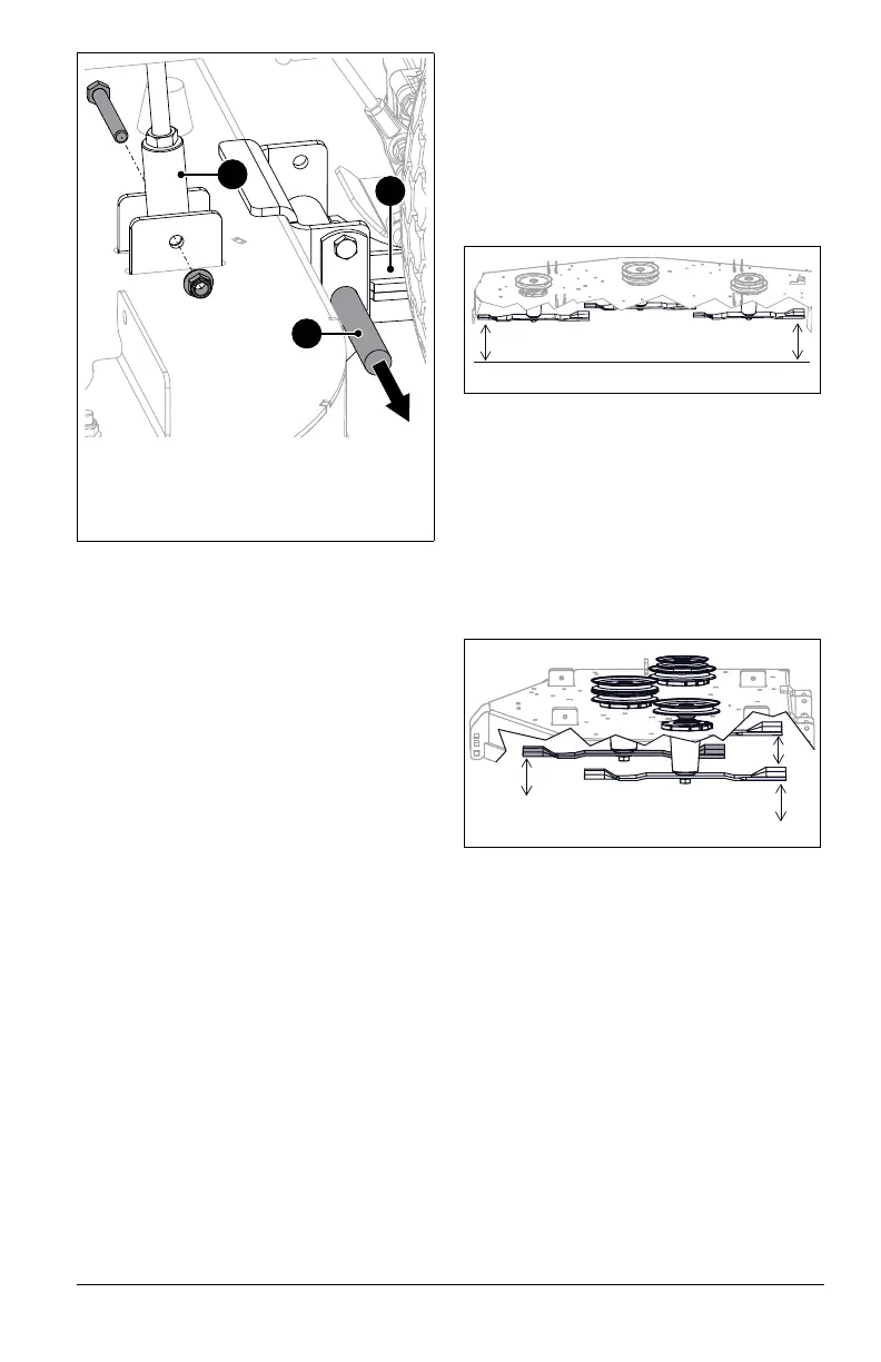
See Figure 57.
1. Position deck under unit.
2. Connect rear mounting arms to deck with
mounting pins.
3. Secure deck lift links to deck lift brackets
with original hardware.
4. Reinstall PTO belt around clutch. See
Install PTO Belt on page 36.
5. Push deck lift pedal completely forward to
engage transport lock.
6.
7. Reconnect lift-assist springs to spring
pegs.
8. Level the deck. See Level and Pitch
Mower Deck on page 39.
LEVEL AND PITCH MOWER
DECK
IMPORTANT: Make sure unit is on a flat,
level surface and that tires are inflated to the
recommended pressures.
Check Blade Level and Pitch
1. Raise deck to 3 1/2" (8.9 cm) cutting
height.
2. Stop engine, remove key and wait for
moving parts to stop and for hot parts to
cool.
3. Engage parking brake.
See Figure 58.
4. Position mower blades so ends point left
to right across the width of the deck.
5. Measure the distance between the
ground and the cutting edge of the left
and right blades. If the measurements are
not within 4.7 mm (3/16") of each other,
level the deck. See Level Mower Deck on
page 39.
See Figure 59.
6. Position mower blades so ends point
front to back and measure the following:
• At the front of the deck, measure the
distance between the ground and the
cutting edge of the middle blade.
• At the rear of the deck, measure the
distance between the ground and the
cutting edge of the left and the right
blades.
If the front measurement is not 3.2 mm (1/8")
lower than the rear measurements, adjust the
blade pitch. See Adjust Blade Pitch on
page 40.
Level Mower Deck
See Figure 60.
1. Adjust the high side of deck:
a. Loosen jam nuts against deck-
leveling links.
b. Turn adjustment bolts
counterclockwise.
c. Measure distance between the
ground and cutting edges of left and
right blades. Continue adjustment if
necessary.
d. Tighten jam nuts against deck-
leveling links.
Figure 57
1. Mounting Pin
2. Deck Lift Link
3. Mounting Arm
1
2
3