DC INVERTER MULTI VRF INSTALLATION
111
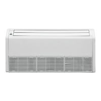
4.2.3 Installation space requirements
GM V(L)-R90T/Na-K
G M V(L)-R 100T/Na-K
G M V(L)-R112T/Na-K
G M V(L)-R125T/Na-K
G M V(L)-R140T/Na-K
GM V(L)-R36T/Na-K
GM V(L)-R45T/Na-K
GM V(L)-R50T/Na-K
≥1500
≥1500
≥1800
340
Model
H
260
H
Ground
surface
Wall
surface
Wall
surfac
Wall
surface
>20
210
unit:m m
GMV(L)-R56T/Na-K
GM V(L )-R63 T/Na-K
GMV(L)-R71T/Na-K
GM V(L )-R80 T/Na-K
GM V(L)-R28T/Na-K
4.2.4 Installation demonstration
1 The primary step for installing the indoor unit.
☆ When attaching the hoisting stand on hoisting screw, do use nut and gasket individually at the
upper and lower of the hoisting stand to fix it. The use of gasket anchor board can prevent
gasket breaking off.
2 Use installation cardboard
☆ Please refer to the installation cardboard about the dimension of ceiling opening.
☆ The central mark of the ceiling opening is marked on the install cardboard.
☆ Install the installation cardboard on the unit by bolt (3 piece), and fix the angle of the drainage
hose at the outlet vent by bolt.
3 Adjust the unit to the suitable installing place. (Refer to the fig.2)
4 Check if the unit is horizontal.
☆ Inner drainage pump and bobber switch are included in the indoor unit. Check if 4 angles of
each unit are horizontal by water level. (If the unit is slant toward the opposite of the coagulate
water flow, there may be malfunction of the bobber switch and leading water drop.)
5 Remove the gasket anchor board used to prevent gasket breaking off and tighten the nut on it.
6 Remove the installation cardboard.
 Loading...