DC INVERTER MULTI VRF CONTROL
7 MONITORING SOFTWARE
7.1 Function
As the development and improvement of manufacturing technology and in order to solve the problems of complex
distribution of the central AC in the buildings and difficult control and maintenance of them, an platform easy and reliable to
operate must be provided to the users for daily management and maintenance. So this long-distance monitoring system
combining electronic communication and computer technologies is developed to collect the running state of the units and to
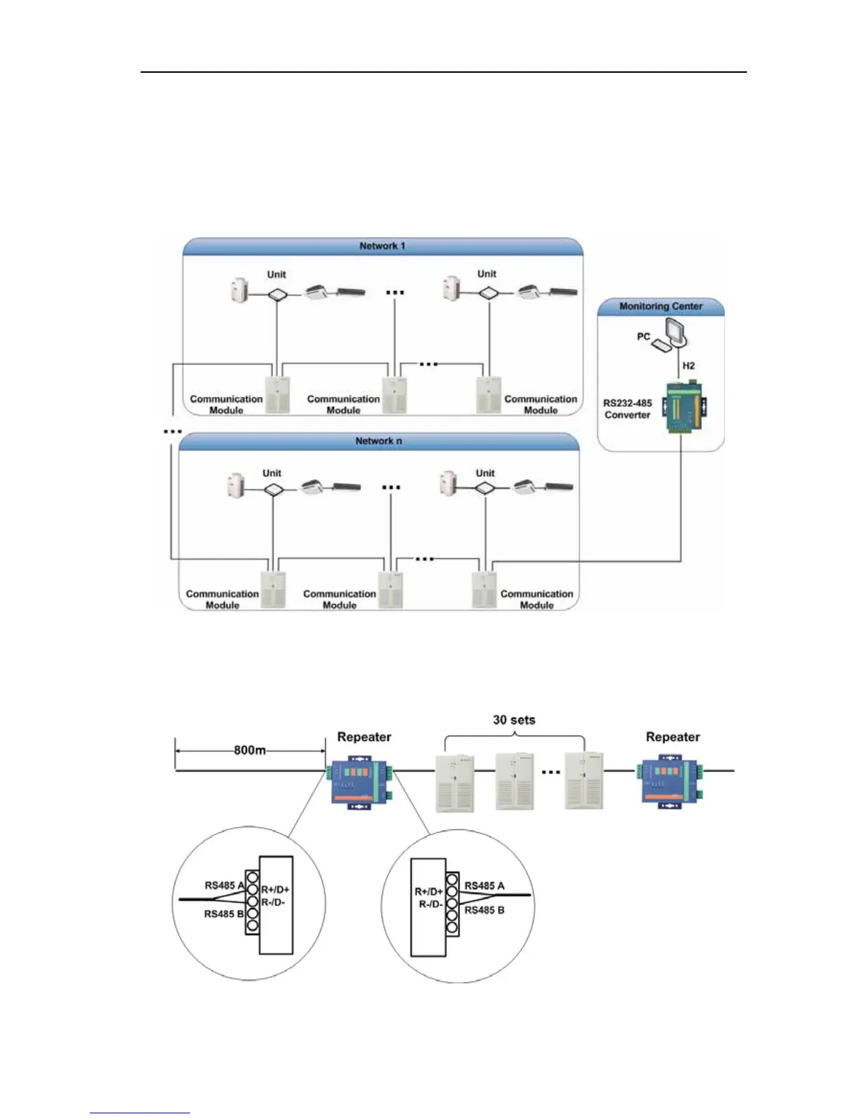
monitor and control the units from a long distance. Its structure is as follow:
7.2 Connection Between the Computer and the Unit
1. Notice:
z The address code of the communication modules should not be conflicted in one project.
z Optoelectronic Isolated Repeater: One every 800m of communication distance equipped with one and one every 30
communication modules equipped with one.
z the communication cable and heavy-current wire should be separated and the distance between them can not be below
15cm
z line A and line B of Bus 485 should respectively correspond with line A and line B.
 Loading...