DC INVERTER MULTI VRF INSTALLATION
160
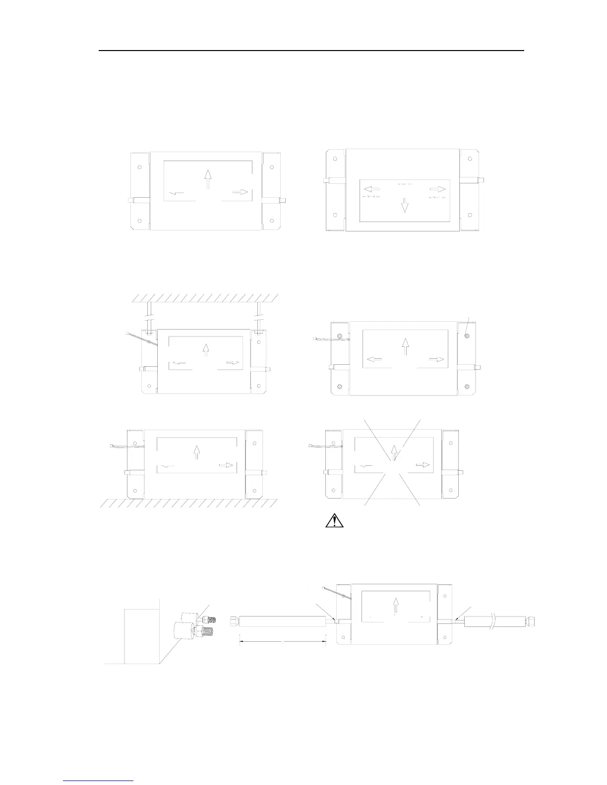
7 INSTALLATION OF ELECTRONIC EXPANSION VALVE ASSY
7.1 Direction Requirements
To ensure normal operation of the unit, please connect the electronic expansion valve
sub-assembly as shown below.
Ensure that the vertical arrow labeled on electronic expansion valve sub-assembly is pointed
upward.
√Arrow Upward X Arrow Downward
(1) Firstly, fix the electronic expansion valve sub-assembly properly. Several operating
methods are available:
Suspend by using screw rod Use screws to fix onto wall②
Directly place on ceiling plane ③
Caution: Never place overhung in air.
The indoor unit shall be firstly connected to a section of pipe (connected by nut). Then, connect
the pipe to the electronic expansion valve sub-assembly (by
welding).
To Indoor
Unit
To Indoor
Unit
To Indoor
Unit
To Indoor
Unit
To Indoor
Unit
To Outdoor
Unit
To Outdoor
Unit
To Outdoor
Unit
To Outdoor
Unit
To Indoor
Unit
To Outdoor
Unit
To Outdoor
Unit
To Indoor
Unit
Verticall
 Loading...