DC INVERTER MULTI VRF CONTROL
72
6.5 Case Study
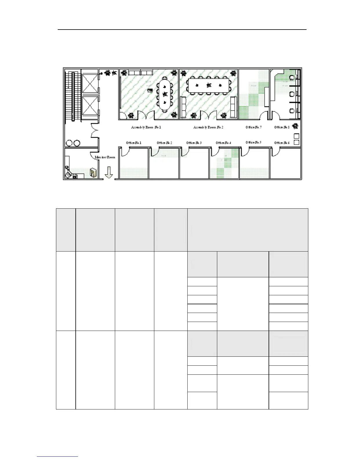
Take one floor of an office building for example to illustrate wiring and debugging of the centralized control system. In
this floor, there are 2 assembly rooms, 8 offices and 1 monitor room. Refer to the following illustration for its plane structure.
1)Instruction to Distribution of Unit and Installation of Equipment
This office building has been installed with 2 sets of GMV units, as shown in the table below.
Name Models
Quantity of
required
communicati
on modules
(pinboard)
Quantity of
indoor
units
Corresponding rooms of indoor units
Room
Address of
communication
module
Address of
indoor unit
Office 1
1,2
Office 2
3,4
Office 3
5,6
Office 4
7,8
Office 5
9,10
Unit1
GMV(L)-Pd160
W/NaB-K
1(0)
12
Office 6
01
11,12
Room
Address of
communication
module
Address of
indoor unit
Office 7 1,2
Office 8
02
3,4
Assembly
room 1
1,2,3,4
Unit 2
GMV-R620W4/
D
2(2)
20
Assembly
room 2
03
5,6,7,8