DC INVERTER MULTI VRF INSTALLATION
133
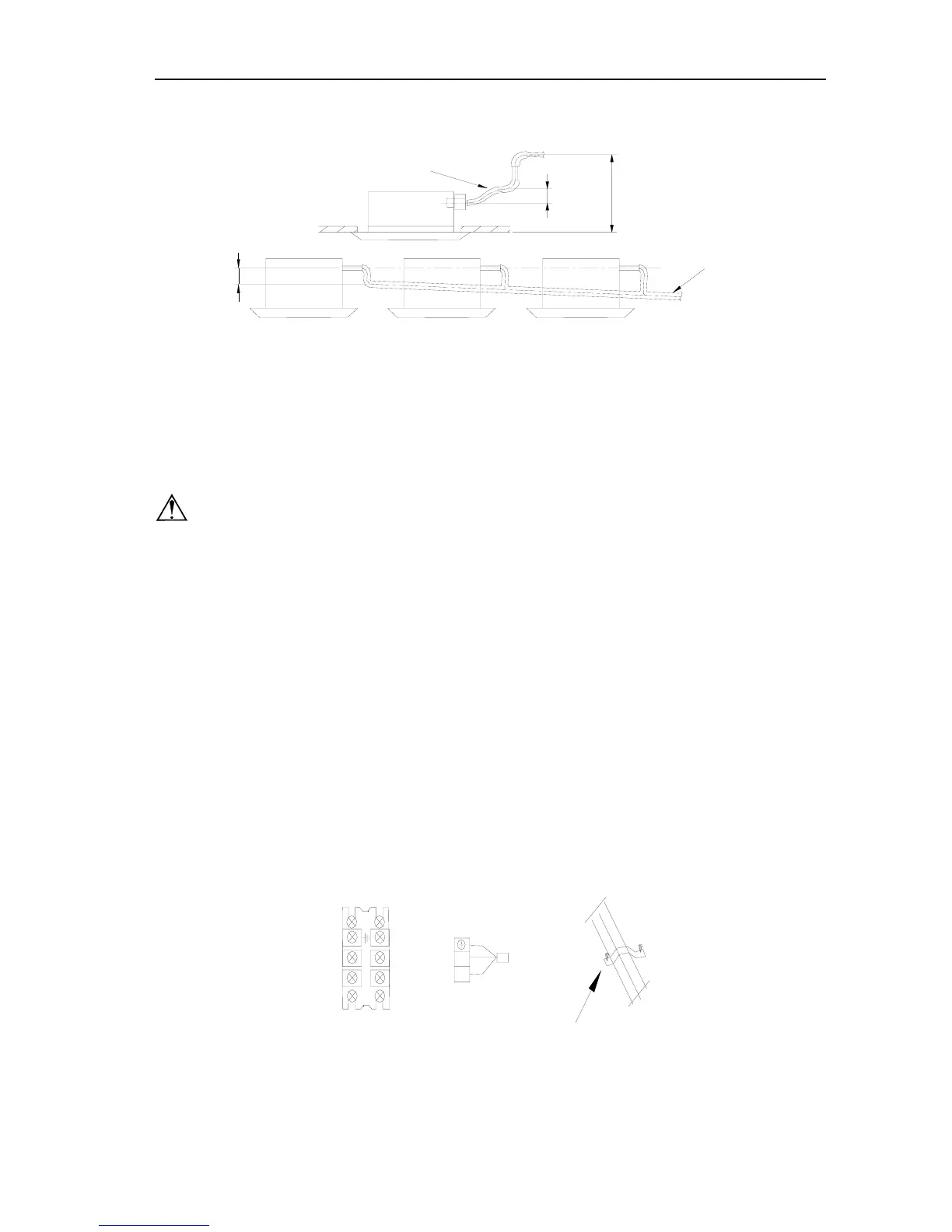
☆ Please install the drain hose according to the following process if several drain hoses join together.
The specs of the selected join drain hose should fits the running capacity of the unit.
.
Above100mm
T-tie in join drain hose
2 Check the smoothness of drain after installation.
☆ Check the drain state by immitting 600cc water slowly from the outlet vent or test hole.
☆ Check the drain in the state of refrigerating after installation of the electric circuit.
● Electrical wiring
Note: The power of the entire indoor unit must be unity power supply
☆ About the electrical wiring, please see the circuit diagram attached with the unit.
☆ All the installation of electrical wiring must be done by professional personnel.
☆ Please do take the earthing treatment.
Wiring method of connection unit and controller
☆ Connection wiring (communication):
① Open electric box cover, drag the wiring (communication)from the rubber plug A, and impact them well
individually by impact fastener.
② Wiring according to the indoor side circuit diagram.
☆ Fix the impact fastener after connection.
☆ Entwine the small sponge on the electric wire ( do entwine it to prevent condensation)
☆ Impact tightly by impact fastener after connection and then fit on the electric box.
☆ Connect the 3 cord rubber wire to the counter terminal of the 3 way terminal board.
3 core rubber wire
N
L
N
power supply
3 core rubber wire
3 way terminal board
Impact fastener
L
● Function description of functional dial switch S7
1. The 3-bit dial switch must be set before energizing the main board and it determines running state of
indoor unit.
below500mm
.
below75mm
Drain hose(attachment)
 Loading...