DC INVERTER MULTI VRF CONTROL
74
Instruction to Frame Diagram of System Net
Mark A:Outdoor Unit GMV(L)-Pd160W/NaB-K can be connected with up to 16 indoor units. In this project, this
outdoor unit is connected with the communication module with address of 01 and indoor units (address 01~12)of office 1-6,
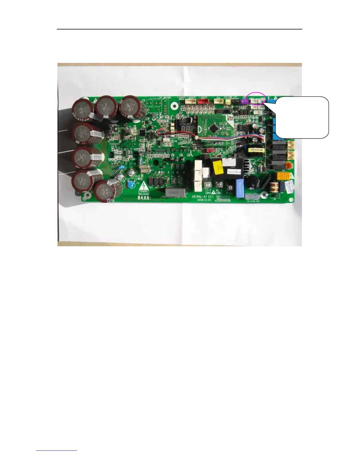
corresponding with independent communication Net.2. The mainboard of outdoor unit is as follow:
Mark B: Outdoor Unit GMV(L)-R620W4/A can be connected with up to 32 indoor units by two pinboards ,either of
which can connect with up to 16 indoor units . What’s more, the quantity of communication modules used is the same as that
of pinboards.
In this project, pinboard 1 is connected with the communication module with address of 02 and indoor units (address
01~04)of office 7-8, corresponding with independent communication Net.2. Pinboard 2 is connected with communication
module of address 03 and indoor units (address 01~08)of office 1-2, corresponding with independent communication Net.3.
The outdoor figure is as follow:
3-core neilsbed
connects with indoor
unit or
communication
module.