50
Multi VRF Indoor
Unit Service Manual
CONTROL
4 RECEIVER
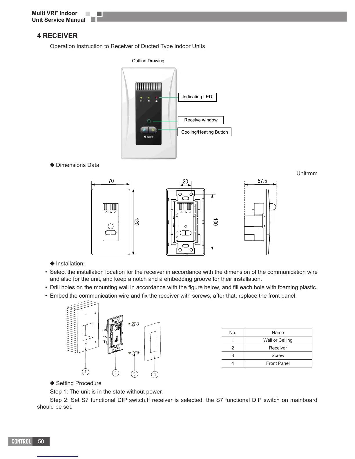
Operation Instruction to Receiver of Ducted Type Indoor Units
Indicating LED
Cooling/Heating Button
Outline Drawing
Dimensions Data
Unit:mm
20
57.570
100
120
Installation:
Select the installation location for the receiver in accordance with the dimension of the communication wire
and also for the unit, and keep a notch and a embedding groove for their installation.
1
2
3
4
Setting Procedure
Step 1: The unit is in the state without power.
Step 2: Set S7 functional DIP switch.If receiver is selected, the S7 functional DIP switch on mainboard
should be set.
No. Name
1 Wall or Ceiling
2 Receiver
3 Screw
4 Front Panel
 Loading...

