GREE GMV5E DC INVERTER VRF UNITS SERVICE MANUAL
63
6.3.3 Insulation for Air Ducts
(1) Insulation for air duct components and devices must be performed after the air leakage test is
performed or after quality check.
(2) Use centrifugal glass wool or rubber and plastic materials for insulation or use novel insulation
air ducts.
(3) The insulation layer should be flat and tight without any crack or gap.
(4) Thickness of the Insulation Layer
For the air supply and return air pipe laid in a room without an air conditioner, thickness of the rubber
and plastic insulation layer is 35 mm.
For the air supply and return air pipe laid in an air conditioning room, thickness of the rubber and
plastic insulation layer is 20 mm.
(5) Supports, hangers, and brackets of the air duct must be installed outside the insulation layer. A
chock must be provided between the support, hanger, or brackets and the air duct.
7 Electric and Controller Installation
7.1 Precautions
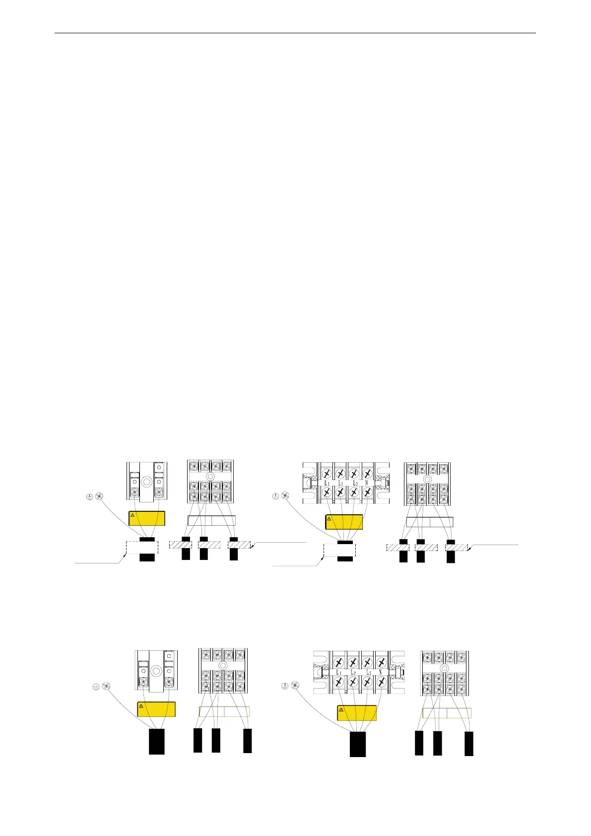
Both the power cable and communication cable must be connected properly. If the power cable is
connected to the communication port, the main board will be burnt.
The power cable and communication cable can be identified in the following ways:
Method 1: Use sheaths in different colours.
L N
L N
D1 D2 H1 H2
D1 D2 H1 H2
Single-phase unit
Grounding
screw
Warning
Warning
1. Reliable grounding is required.
2. The screw for fixing the conducting
wire must be tightened. It must be
replaced if slipped screw head exists.
3. The external conducting wire must
be fixed by a clip. Otherwise, personal
injury or fire may occur.
1. Reliable grounding is required.
2. The screw for fixing the conducting
wire must be tightened. It must be
replaced if slipped screw head exists.
3. The external conducting wire must
be fixed by a clip. Otherwise, personal
injury or fire may occur.
Power cable
Indoor/outdoor unit
communication D1 D2
Wired controller
H1 H2
Indoor/outdoor unit
communication D1 D2
Wired controller
H1 H2
Power cable
Grounding
screw
Indoor/outdoor
communication cable
Communication cable
of the wired controller
Indoor/outdoor
communication cable
Communication cable
of the wired controller
Color label for the
communication cable
Color label for the
communication cable
Color label for
the power cable
Color label for
the power cable
Three-phase unit
Method 2: Use different types of cables.
The diameter of the power cable is larger than that of the communication cable. Alternatively, adopt
three cores or more for the power cable and two cores for the communication cable.
L N
L N
D1 D2 H1 H2
D1 D2 H1 H2
Single-phase unit
Grounding
screw
Warning
1. Reliable grounding is required.
2. The screw for fixing the conducting wire
must be tightened. It must be replaced if
slipped screw head exists.
3. The external conducting wire must be
fixed by a clip. Otherwise, personal injury
or fire may occur.
Power cable (three-core)
(The yellow green cable
is the ground cable.)
Indoor/outdoor unit
communication D1 D2
Wired controller
H1 H2
Indoor/outdoor
communication
cable (two-core)
Communication
cable of the wired
controller (two-core)
Three-phase unit
Grounding
screw
Power cable (five-core)
(The yellow green cable
is the ground cable.)
Indoor/outdoor
communication
cable (two-core)
Communication
cable of the wired
controller (two-core)
Indoor/outdoor unit
communication D1 D2
Wired controller
H1 H2
Warning
1. Reliable grounding is required.
2. The screw for fixing the conducting wire
must be tightened. It must be replaced if
slipped screw head exists.
3. The external conducting wire must be
fixed by a clip. Otherwise, personal injury
or fire may occur.

 Loading...