GREE GMV5E DC INVERTER VRF UNITS SERVICE MANUAL
80
⑨ DIP Switch Example
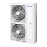
A. Explanation of DIP switch positions
On the DIP switch, “ON” indicates “0” status and the opposite direction indicates "1” status.
The position of white lever indicates the position to be set to.
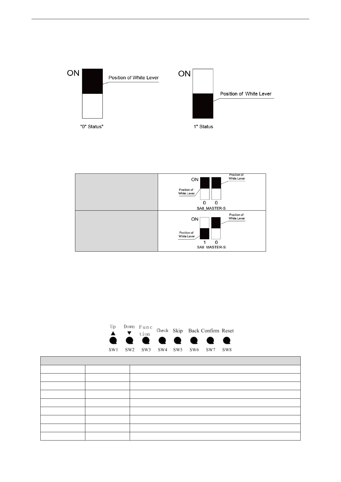
B. Example
The following takes master unit settings as an example. Assume that a system consists of three
modules: module a, module b, and module c. Set module c to master unit and the other two modules to
sub-modules. The settings are as follows:
Module a/Module b (Sub-module)
2.2 System Function Button Operations
Note:
① System function settings and query must be performed after commissioning of the entire unit.
② System function settings and query can be used no matter whether the entire unit runs.
2.2.1 Introduction to Function Buttons
The main board AP1 of the ODU consists of eight function buttons:
Function Button Name and Meaning
Indicates the upward selection button.
Indicates the downward selection button.
Indicates the function button, used for function settings.
Indicates the query button, used for function query.
Indicates the skip button.
Indicates the return button, used to return to the upper-level menu.
Indicates the confirmation button.
Indicates the reset button, used to restore factory settings.

 Loading...