EasyManua.ls Logo

GREEN INSTRUMENTS G36 - Relay Outputs - D-OUT; Figure 5-1: Terminals Pc-Board - 100 - 230 Vac

GREEN INSTRUMENTS G36
47 pages
Print Icon
To Next Page IconTo Next Page
To Previous Page IconTo Previous Page
Loading...
Installation & Connections
14
SD-CARD RS-232
FUSE 3
2AT/250 V
FUSE 2
2AT/250 V
FUSE 1
2AT/250 V
CAN 100–230 VAC
1.+24VDC
2.1 NC
3.1 COM
4.1 NO
5.2 NC
6.2 COM
7.2 NO
8.3 NC
9.3 COM
10.3 NO
11.4 NC
12.4 COM
13.4 NO
14 GND
L N
6. DIGITAL IN 3
7. DIGITAL IN 4
8. GND
3. + 24 VDC
4. DIGITAL IN 1
5. DIGITAL IN 2
4. A-OUT 2 +
5. A-OUT 2 –
1. A-OUT 1 +
2. A-OUT 1 –
3. NOT USED
6. GND
5. Oxygen
HEAT
GREEN
Instrume
nts A/S
www.Greeninstrume
nts.com
4. NOT
USED
3. Oxygen
2. Oxygen
1. Oxygen
1. ANALOG IN 1
2. ANALOG IN 2
D-OUTSEN
INPUT
A-OUT
ETHERNET
(OPTIONAL)
PE
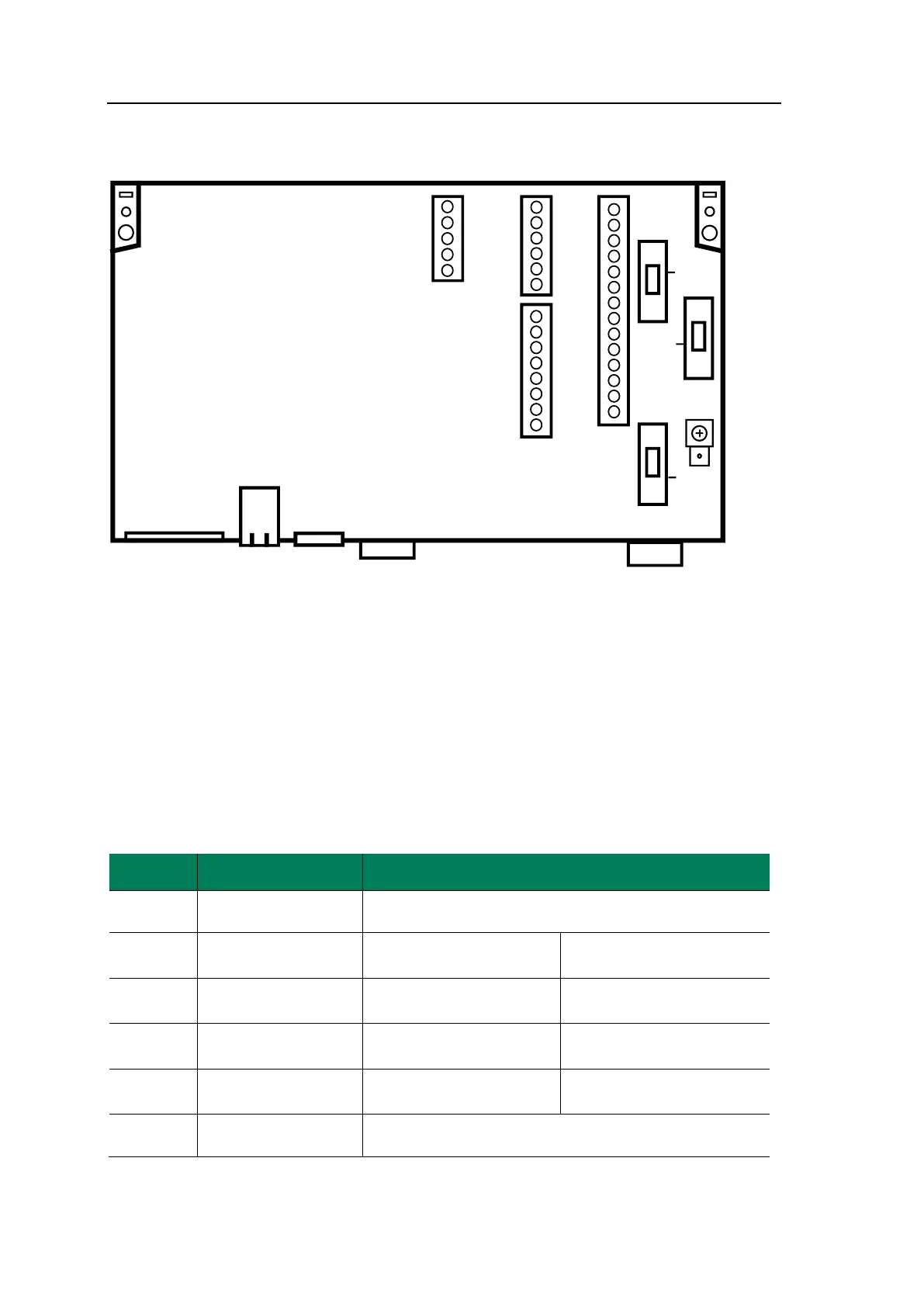
Figure 5-1: Terminals PC-Board - 100 - 230 VAC
5.2.3 Relay Outputs D-OUT
The analyzer is arranged with four relay outputs connected to D-OUT with 14 terminals.
It is important to note that the configuration of the analyzer might deviate from the con-
figurations listed below. Please see the Testing & Configuration Sheet that is attached to
each analyzer.
The default relay functions, and connections of the Inert Gas Oxygen Analyzer are as fol-
lows:
Relay No.
Relay function
Terminal Connections
Internal power supply
+ 24 VDC
Terminal 1
Relay 1
Alarm High/Low O
2
level
Terminals 2.1-3.1-4.1
(NC-COM-NO)
Inverted
Normally energized
Relay 2
Alarm High High O
2
level
Terminals 5.2-6.2-7.2
(NC-COM-NO)
Inverted
Normally energized
Relay 3
System failure alarm
Terminals 8.3-9.3-10.3
(NC-COM-NO)
Inverted
Normally energized
Relay 4
Calibration Span Gas
Terminals 11.4-12.4-13.4
(NC-COM-NO)
Normally
de-energized
Internal power supply
ground
Terminal 14

Table of Contents