Installation & Connections
16
5.2.4 Input Connections – INPUT
The input connections (INPUT) are placed right below the sensor connections SEN. The
terminal is arranged with 8 poles for 2 analog inputs and 4 digital inputs. The configura-
tion is as follows:
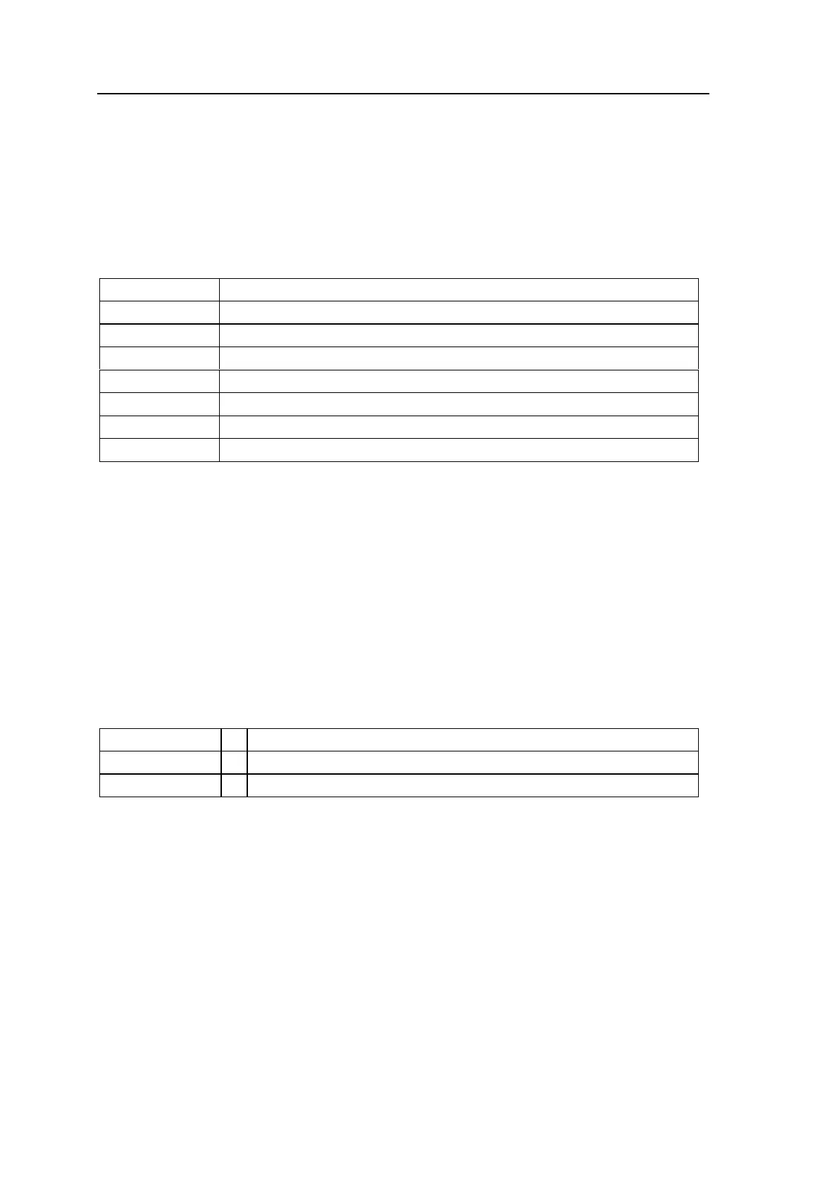
Ai01 – Analog Input 1 for connection of a passive 4-20 mA signal*
Ai01 – Analog Input 1 for connection of an active 4-20 mA signal**
Ai02 – Analog Input 2 for connection of a passive 4-20 mA signal*
Ai02 – Analog Input 2 for connection of an active 4-20 mA signal**
Di00 – Digital Input 1 for connection of an NPN input
Di01 – Digital Input 2 for connection of an NPN input
Di02 – Digital Input 3 for connection of an NPN input
Di03 – Digital Input 4 for connection of an NPN input
* Passive input signal means signal voltage from the G36 analyzer.
** Active input signal means signal voltage from external source.
As an option, digital input 1 can be set up for artificial calibration, and/or digital input 2
can be set up for back-flushing.
For setting the analog inputs please see appendix 12.1.
5.2.5 Analog Output Connections – A-OUT
There are two active 4…20 mA output signals*** for load up to 600 ohm. The configura-
tion is as follows:
Analog Output 1 for the remote indication of oxygen level
Analog Output 2 (optional)
*** Active output signal means signal voltage from the G36
analyzer.
For setting of analog outputs please see section 0.
5.2.6 SD Card
The SD card is used for storage of the historical trend of O
2
and the logbook. The SD
card can also be used to load a new software version to the analyzer.
Data log
The internal memory of the analyzer measures and saves six values every minute. How-
ever, the internal memory can only store one hour of logging, which is equal to 360 log
values. If there is no SD card installed the new log values will supersede the old log val-
ues. This means there will be no historical trend curve and alarm logs as well.