55
Power and Data Transmission Unit
7.8.1 IO10 module inputs
Two IO10 modules can be connected to SECUREconnect 100R via terminals LA and LB.
Input and output parameters are preset in compliance with the GU-BKS-NET concept.
Basic settings of IO10 address 1:
Input Function
Input 1: terminal I1, V9 Permanent OPEN
Input 2: terminal I2, V9 Close
Input 3: terminal I3, V9 Priority locking
Input 4: terminal I4, V9 Priority unlocking
Basic settings of IO10 address 2:
Input Function
Input 1: terminal I1, V9 Non-priority unlocking
Input 2: terminal I2, V9 -
Input 3: terminal I3, V9 Short-time OPEN
Input 4: terminal I4, V9 -
7.8.2 IO10 module outputs
The input statuses (SECUREconnect 100F) are put out directly to the IO10 module relays.
Basic settings
Input
(SECUREconnect 100F)
Output
IO10 address 1
Input 1: terminal I1, V4 Relay 1: terminal 41, 51, 61
Input 2: terminal I2, V4 Relay 2: terminal 42, 52, 62
Input 3: terminal I3, V4 Relay 3: terminal 43, 53, 63
Input 4: terminal I4, V4 Relay 4: terminal 44, 54, 64
Input
(SECUREconnect 100F)
Output
IO10 address 2
Input 1: terminal I1, V4 Relay 1: terminal 41, 51, 61
Input 2: terminal I2, V4 Relay 2: terminal 42, 52, 62
Input 3: terminal I3, V4 Relay 3: terminal 43, 53, 63
Input 4: terminal I4, V4 Relay 4: terminal 44, 54, 64
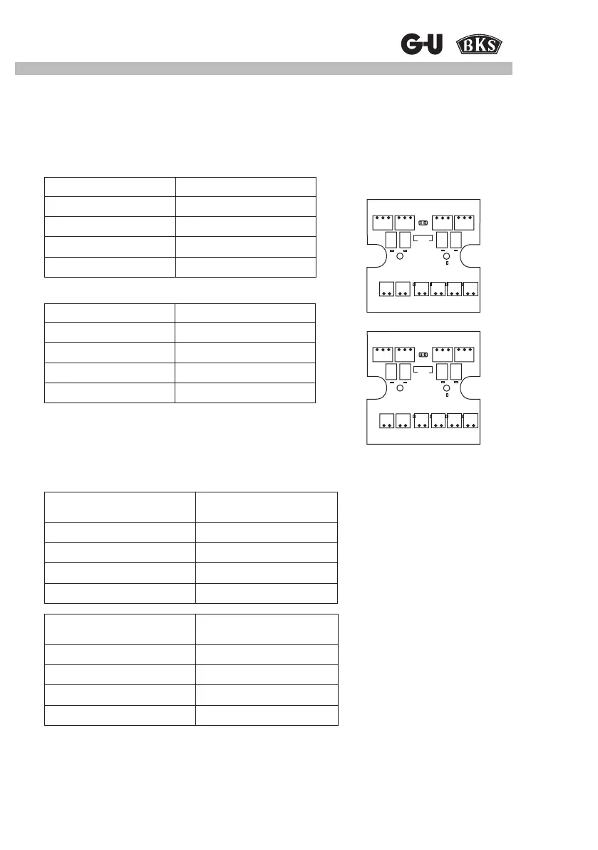
Service
61 41 51 62 42 52 63 43 53 64 44 54
G1 V1 LA LB V9 I1 V9 I2 V9 I3 V9 I4
Service
61 41 51 62 42 52 63 43 53 64 44 54
G1 V1 LA LB V9 I1 V9 I2 V9 I3 V9 I4