GRISWOLD PUMP COMPANY Installation Page 9
Installation, Operation and Maintenance Manual
Griswold Model 811
Griswold Pump Company Installation Page 11
Suction Piping – Suction Lift Installations
1. Suction lines when operating under lift
conditions must be absolutely free from
air leaks.
2. Suction piping should gradually slope
upward toward the pump.
3. NPSH available must be greater than the
NPSH required by the pump.
4. A means of priming the pump, such as a
foot valve, must be provided.
5. Pipe must be supported properly to
prevent flange loading.
6. Provide adequate submergence over the
suction pipe inlet to prevent formation
of vortices.
Suction Piping – with Positive Head (Flooded Suction)
1. The suction line must include an isolation valve to close off the source of supply when
performing inspection or maintenance on the pump. Install this valve at least two pipe
diameters before the pump suction nozzle.
2. Piping should be level or gradually slope downward from the suction source in order to
avoid air pockets.
3. Attention should be paid to the design of the exit from the supply source to prevent the
formation of vortices or eddies that can draw air into the pump. This relates to the
velocity of the outflow and the submergence of the supply exit below the liquid level.
Discharge Piping
1. Discharge piping will normally be larger than the pump discharge size, so a concentric
increaser is usually used for adaptation. Locate increaser below check valve.
2. A check valve and isolation valve should be located in the discharge line. The check
valve should be located between the isolation valve and the pump. This will prevent back
flow through the pump (reverse rotation) and will also serve to reduce any back pressure.
3. If an expansion joint is used, it should be located between the check valve and the pump.
Proper anchoring is necessary.
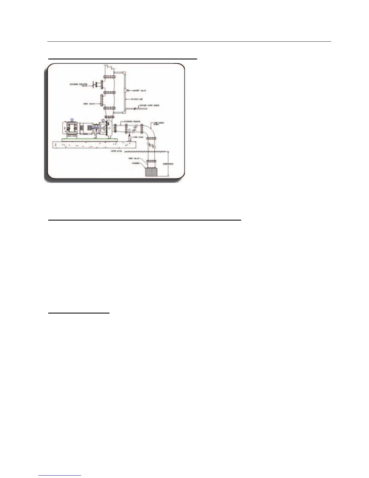
FIGURE 5