GRISWOLD PUMP COMPANY Appendix Page 53
Installation, Operation and Maintenance Manual
Griswold Model 811
Griswold Pump Company Appendix Page 52
If the end plate (pump end) was previously installed, make any necessary adjustments to the
coupling and skip to Step 2.
Before assembling or disassembling the coupling guard, de
motor controller/starter, and place a caution tag at the starter indicating that it is
disconnected. Before resuming normal pump operation, replace the coupling guard.
Griswold Pump assumes no liability when this procedure is not followed..
ANSI B15.1 COUPLING GUARDS
ASSEMBLY PROCEDURES
1. On the 811S, 811M, and 811L, bolt the end plate (pump end) to the bearing frame.
(Impeller adjustment will not be affected.)
On the 811XL, bolt the end plate (pump end) to
the pump bearing housing with the small slots on
the end plate aligned to the impeller adjusting
bolts and the large slots clearing the bearing
housing tap bolts. Then attach the end plate to the
bearing housing using the jam nuts on the
impeller adjusting bolts as shown in Figure A-2.
After attaching the end plate to the bearing
housing, check and reset the impeller clearance
as detailed in APPENDIX. 1 - IMPELLER
CLEARANCE SETTING
.
2. Slightly spread the bottom of coupling
guard half (pump end) and place it
over the pump end plate as shown in
Figure A-3. The support slots in the
guard half are located around the end
plate.
3. After placing the coupling guard half
around the end plate, secure it with a
bolt, nut and two (2) washers through
the round hole in the front end of the
guard half as shown in Figure A-3.
Tighten securely.
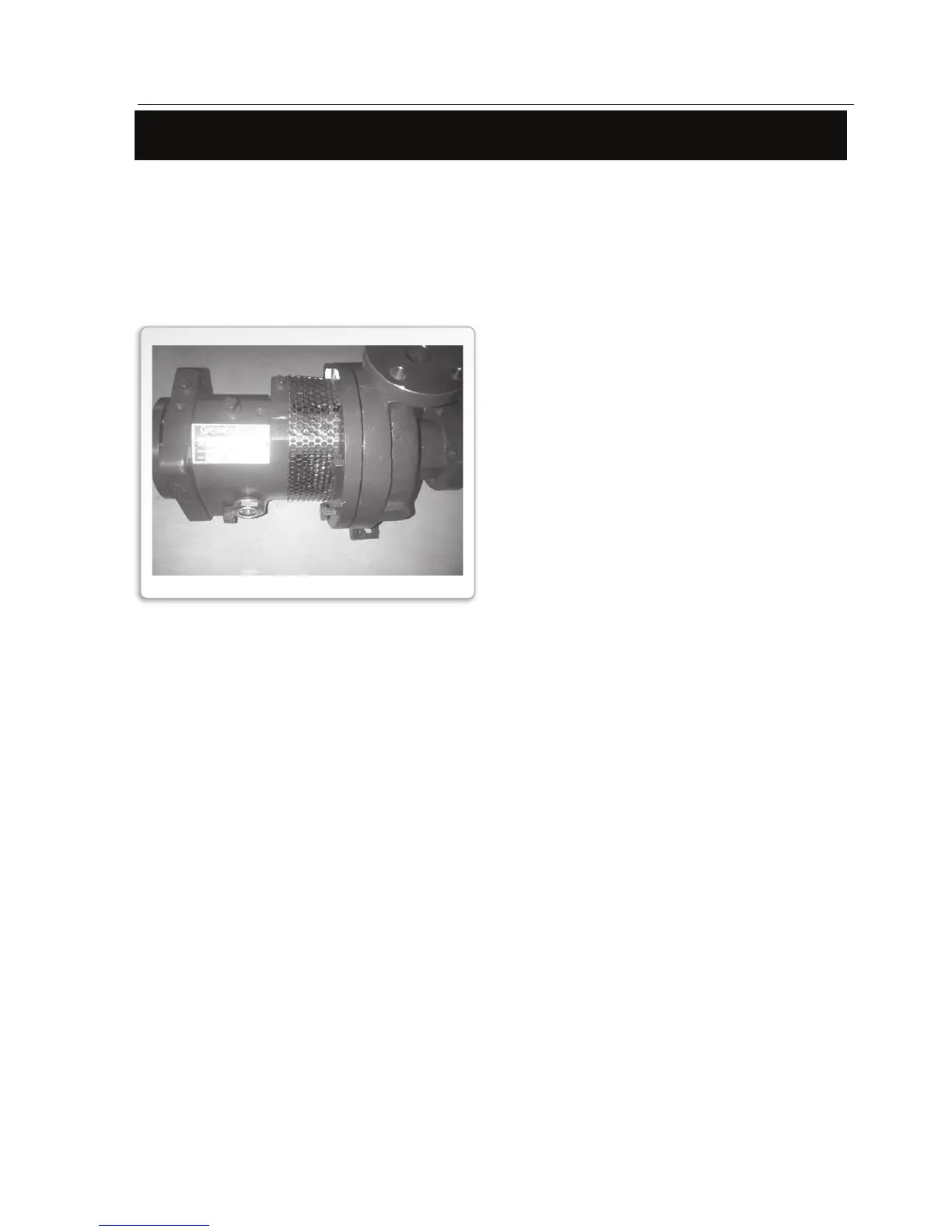
Seal Guard
Seal guards (shown below) are available when all rotating shaft components must be covered.
This option is required for all CE pump models.
When ordered, the pump will be shipped with the seal guard installed. The seal guard is sup-
plied with captive fasteners to secure the guard in place.
Prior to startup, ensure that the guard has not been removed, damaged, or loosened during trans-
portation, loading/unloading, installation, etc.
Never loosen or remove the seal guard during operation.
Before removing the seal guard for pump maintenance, de-energize the motor, lock out the mo-
tor controller/start and place a caution tag at the starter indicating that it is disconnected. Before
resuming normal pump operation, replace the seal guard.
For maintenance, the guards can be removed by loosening the captive fasteners.