GRISWOLD PUMP COMPANY Appendix Page 38
Installation, Operation and Maintenance Manual
Griswold Model 811
Griswold Pump Company
Appendix Page 40
Drive power must be locked out to prevent accidental start-up and physical injury.
Drive power must be locked out to prevent accidental start-up and physical injury.
Impeller Clearance Adjustment
Feeler Gauge Method
1. Lock out power supply to motor.
2. Remove coupling guard and coupling
spacer.
3. Loosen jack bolts (370D) and jam nuts
(423).
4. Tighten bearing housing bolts (370C)
evenly, while slowly rotating the shaft until
the impeller just starts to rub on the casing.
5. Using a feeler gauge set the gap between the
three housing bolts (370C) and the bearing
housing. Set the gap according to the table,
below, as required.
6. Tighten jacking bolts (370D) evenly, until
bearing housing backs out and contacts the bearing housing bolts (370C).
7. Tighten jam nuts (423) evenly. Rotate shaft to make sure that it turns freely.
8. Reinstall coupling spacer and coupling guard.
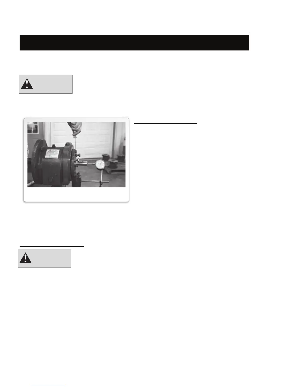
Dial Indicator Method
1. Lock out power supply to motor.
2. Remove coupling guard and coupling spacer.
3.
Place a dial indicator with a magnetic mounting base on the surface of the pump baseplate. Position
indicator against face of pump shaft.
4. Loosen jacking bolts (370D) and jam nuts (423).
5. Tighten bearing housing bolts (370C) evenly, while slowly rotating the shaft until the
impeller just starts to rub on the casing. Set dial indicator to zero.
6. Tighten the jacking bolts (370D) evenly, until they contact the bearing frame. Continue to
tighten the jacking bolts evenly, about one flat at a time, drawing the bearing housing away
from the frame until
the dial indicator shows the proper clearance
APPENDIX - I
Feeler Gauge Method
Installation, Operation and Maintenance Manual
Griswold Model 811
Griswold Pump Company Appendix Page 42
Use non-foaming and non-detergent oils only.
Recommended Lubricants
Lubricating Oil Requirements
Pumpage temperature
< 350
0
F
Pumpage temperature
> 350
0
F
ISO Grade VG 68 VG 100
Approx. SSU @ 100
0
F 300 470
DIN 51517 C68 C100
Kinematic Viscosity @100
0
F
mm
2
/sec
68 100
Some acceptable lubricating oils:
Chevron GTS Oil 68
Exxon TERRESTIC 68 or NUTO H68
Mobil DTE Heavy-Medium
Philips Mangus 315
Shell Tellus Oil 68
Sunoco Sunvis 968
Amoco Amoco Industrial #68
Royal Purple SYNFILM ISO VG68
Change oil after 200 hours of initial operation, then every 2000 hours or three (3) months
thereafter, whichever occurs first.
Bearing Frame Oil Capacity
Frame Pints
S 1.0
M 2.6
L 3.0
XL 7.4
Capacities are approximate. Do not over fill the oil sump as this will cause overheating and
damage the bearings. Fill to the centerline of the sight glass.
WARNING
WARNING
FIGURE A-1
FEELER GAUGE METHOD