GRISWOLD PUMP COMPANY Installation Page 10
Installation, Operation and Maintenance Manual
Griswold Model 811
Griswold Pump Company Installation Page 12
Driver power must be locked out b
efore beginning any alignment procedure. Failure to lock
out driver power may result in serious physical injury.
Proper alignment is the responsibility of the installer and user of the equipment.
Check alignment if process temperature changes, piping changes and/or pump service is
performed.
Alignment of Pump/Driver Shafts
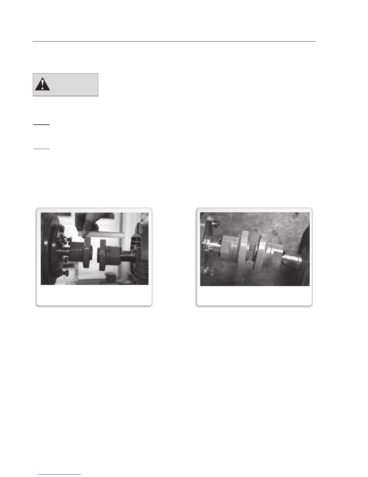
Pump and driver shafts need to be aligned for both parallel and angular alignment. If there is a
misalignment of the shafts, it will place a mechanical load on the pump and driver shaft/bearing
assemblies as well as the coupling. This will result in vibration, noise and premature failures.
To bring shafts into alignment, we first need to determine the amount and direction of both
parallel and angular misalignments. We can then shim and reposition to correct.
It’s preferable to shim ONLY under the driver feet since good contact between the pump feet and
the base is necessary to resist any pump flange loading that might be imposed by the suction
and/or discharge piping.
There are three methods commonly used to determine misalignment:
1. Straight edge and calipers or inside micrometer (least accurate)
2. Dial indicator (reasonably accurate)
3. Laser Alignment Equipment. See manufacturer’s instructions for use.
WARNING
FIGURE 6
PARALLEL MISALIGNMENT
FIGURE 7
ANGULAR MISALIGNMENT