GRISWOLD PUMP COMPANY Installation Page 6
Installation, Operation and Maintenance Manual
Griswold Model 811
Griswold Pump Company Installation Page 8
Installation
The pump location should be clean, well ventilated, properly drained and allow room for
maintenance and inspection.
Trouble-free operation of a pump begins with proper installation with particular attention being
paid to the baseplate and piping attachments. A secure baseplate will enable accurate alignment
to be attained and maintained. Flange loads from misaligned or improperly supported piping
will make alignment difficult and will cause premature failures.
Baseplates and Anchors
The preferred mounting for a baseplate is on a concrete pad with grouting. No matter how robust
its design, there is always some flexibility in the baseplate itself. If there is insufficient support
under the baseplate, it can distort causing alignment difficulties and normal vibrations can be
amplified to unacceptable levels through resonances in the pump support and/or piping. A
properly grouted baseplate will resist distortion and will provide sufficient mass to dampen any
vibration.
Anchor (foundation) bolts are used to hold the baseplate to its support structure, whatever that
may be. In the preferred case of mounting the pump unit on a concrete pad, the anchor bolts are
set into the pad as indicated in the following illustration. When pouring the pad, it’s helpful to
have a wooden template attached to the foundation form to position the anchor bolts at their
locations as indicated on the pump unit assembly drawing.
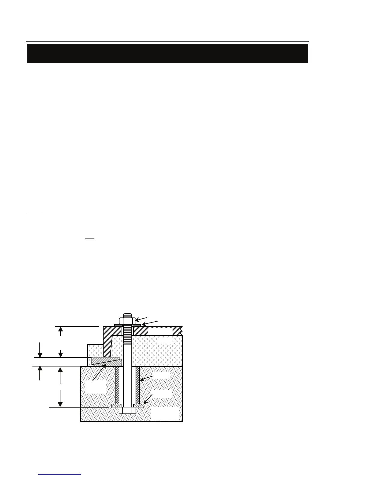
Typical Anchor Bolt (Sleeve Type)
Baseplate
Grout
Sleeve
Washer
Washer
Nut
Drawing
12" - 18"
Wedges
Anchor bolts are usually sized
than the anchor bolt hole size in the base.
Calculate bolt length as indicated in
Figure 4 at the left.
The ID of the sleeve should be two bolt
sizes larger than the anchor bolt.
- 1½" space between
the bottom edge of the baseplate and the
A “Sleeve” type anchor bolt is shown
here. Alternatively, a “hook” or “J” type
anchor bolt may be used.
Pack the space between the anchor bolt
and sleeve to prevent concrete and/or
grout from entering this area.
When pumps and motors are assembled on a baseplate at the factory, a preliminary
alignment is done to ensure that the pump and motor can be aligned at its installation.
This alignment is not to be considered as a final alignment. The factory alignment can,
and does, change during shipment and when the pumping unit is installed. Actually,
several alignments are necessary as will be described later.