GRISWOLD PUMP COMPANY Appendix Page 43
Installation, Operation and Maintenance Manual
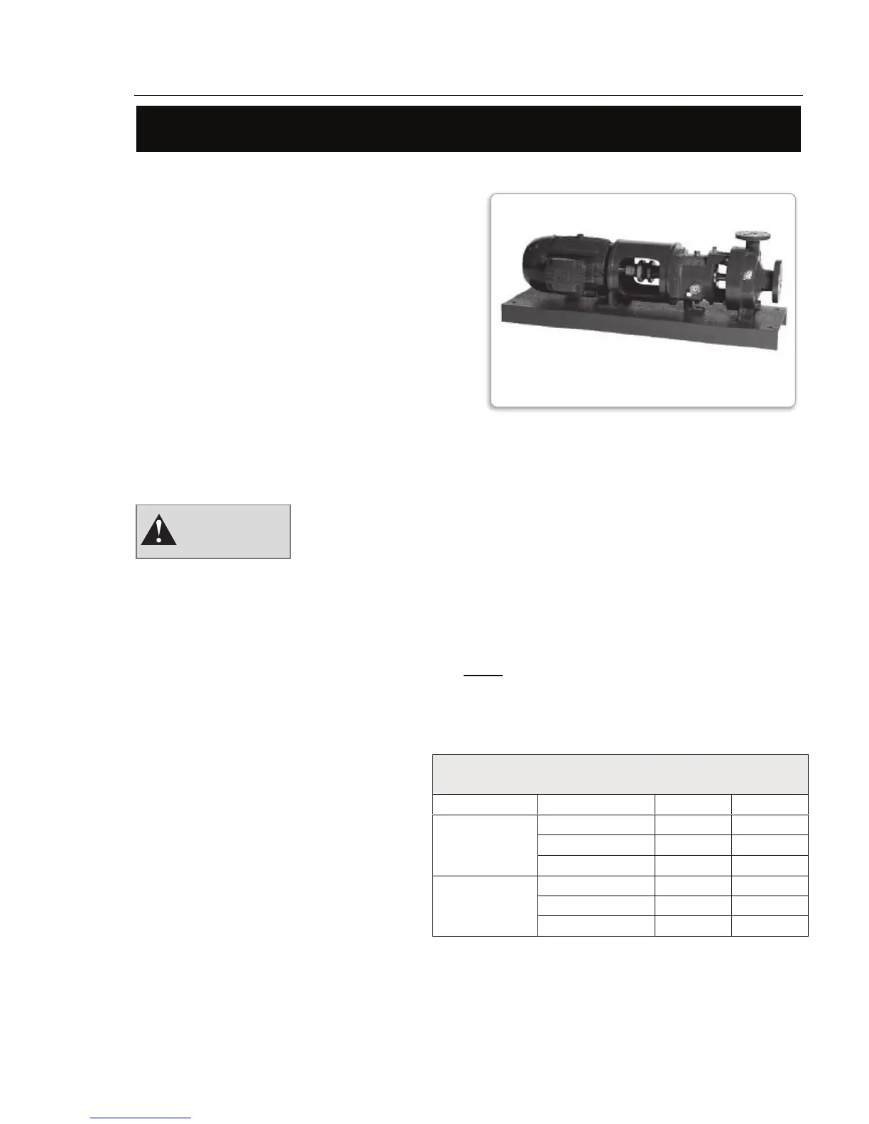
Griswold Model 811
Griswold Pump Company Appendix Page 45
The motor may be heavy and should be properly supported
with a clean, uncorroded eye bolt or a strap under both end
bells.
Note:
It is not necessary to remove the pump
and motor coupling hubs.
C-Face Adapter
The C-Face motor adapter attaches to the rear of
the bearing frame of the pump. This feature
enables a C-flange motor to be attached and
ensures alignment between the pump and motor
shafts.
The C-Face motor adapter may have a mounting
foot with an overhung motor or the motor may
be supported on its own feet where the adapter is
unsupported.
Disassembly
Remove guard.
Remove the motor by loosening the motor
mounting bolts (371).
Remove the C-Face adapter (340)
from the pump-bearing frame
(228A) by loosening the four
bolts (371N) attached to the
bearing frame flange.
Inspect the adapter for signs of corrosion,
cracking, scale or debris. Clean accordingly.
C-Face Adapter
Bolting Torque, Ft.-Lbs.
Bolt Frame Dry Lubed
S 30 20
M 30 20
Adapter to
Pump Frame
L 30 20
143TC-145TC 12 8
182TC-286TC 30 20
Motor to
Adapter
324TC-365TC 59 39
Mount both the pump and motor
coupling hubs if not already mounted.
Slide the C-Face adapter (340) over
the pump shaft (122) and mount
against the pump bearing frame
(228A) flange using four bolts
(371N). Torque bolts to the values
shown in table.
Mount the motor to the C-Face
adapter (340) using the four or eight
motor bolts (371). Torque bolts to
the values shown in table. Reinstall
guard.
WARNING
C-FACE ADAPTER
WITH MOTOR AND PUMP