GRISWOLD PUMP COMPANY Repair Maintenance Page 21
Installation, Operation and Maintenance Manual
Griswold Model 811
Griswold Pump Company Repair Maintenance Page 23
Disassembly and Reassembly Warnings
Prior to working on this or any pump note the following safety precautions and warnings:
Warnings and Precautions!
Lock out power supply. Close suction and discharge valves.
Pump components can be heavy. Proper
lifting methods must be used to avoid physical
injury and equipment damage.
Wear steel-toe shoes, safety glasses, gloves
and any other required protective clothing.
If the pump contains toxic or hazardous
fluids, proper personal protective equipment
must be worn.
Toxic or hazardous materials must be handled
and disposed of properly in accordance with all
applicable environmental regulations.
Never apply heat to remove parts. Trapped
liquid may cause an explosion and cause
physical injury.
Allow system components to cool before
handling.
The Griswold Model 811 is an ANSI B73.1 design, which is back pull-out. The pumping
assembly (back pull-out assembly) can be removed from service without disturbing the casing or
the driver. An exception to this would be when a C-face adapter is used to support the electric
motor and keep the pump and motor shafts in alignment.
Removing Pump from Service
1. Lock out power supply.
2. Close suction and discharge valves.
3. Drain liquid from casing and flush as necessary or required. If liquid is toxic or hazardous,
wear appropriate protective equipment and handle liquid properly!
4. Remove coupling guard and coupling spacer as stated in Appendix IX.
5. If oil-lubricated, remove drain plug, drain oil and replace drain plug.
6. Disconnect any flushing or cooling lines.
7. Remove frame foot hold-down bolts.
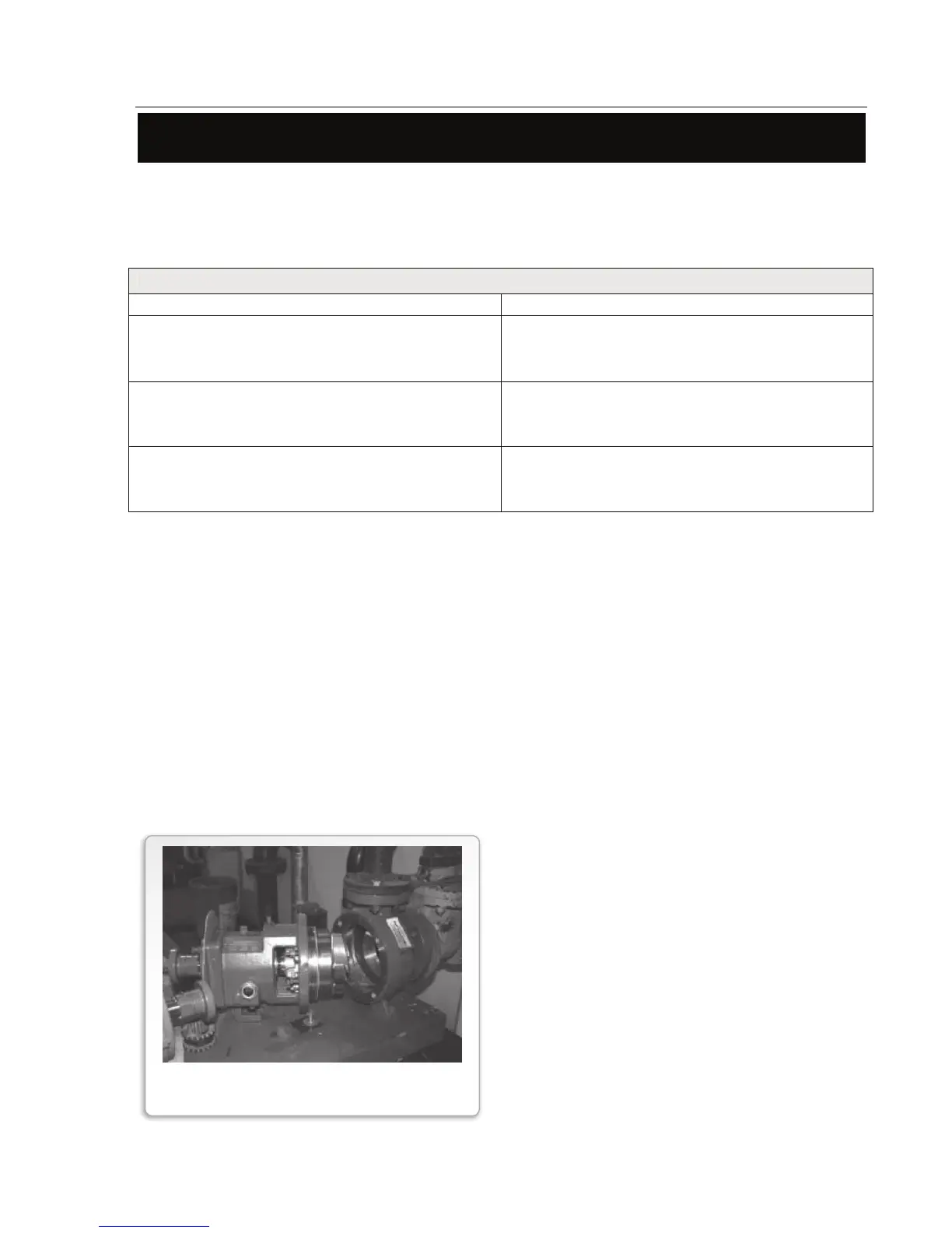
8. Remove complete back pull-out assembly by
removing frame adapter-to-casing bolts (Item
370) and tightening jacking screws (Item
418). Support back pull-out assembly with
appropriate lifting device(s).
9. Inspect casing internals for wear.
10. Using suitable lifting device(s), transport
back pull-out assembly to maintenance area.
FIGURE 12
BACK PULL-OUT REMOVAL