GRISWOLD PUMP COMPANY Repair Maintenance Page 22
Installation, Operation and Maintenance Manual
Griswold Model 811
Griswold Pump Company Repair Maintenance Page 24
Disassembly
Required tools:
Open End Wrenches Impeller Wrench Induction Bearing Heater
Snap Ring Pliers Spanner Wrench Allen Wrenches
Dial Indicator Micrometer Torque Wrench
Feeler Gages Drift Punch Hoist
Bearing Puller Rubber Mallet Screwdriver(s)
Hydraulic Press Cleaning Agents
Impeller Removal
1. Secure pump/back pull-out assembly to work bench.
2. Scribe line on pump shaft at end of coupling hub and proceed to remove hub from shaft.
3. Remove impeller (Item 101) Do not apply
heat. Use impeller shaft wrench for S and M
frames. (Note: For L and XL frames use a
spanner wrench or other suitable tool that
will not mark the shaft.) Slide wrench over
shaft (Item 122) and key (Item 400). Turn
impeller clockwise (viewed from impeller
end of shaft), to raise wrench off of
workbench. Abruptly turn impeller
counterclockwise to impact wrench against
workbench or block of wood. Repeat as
necessary until impeller loosens on shaft
threads. Spin off impeller and discard o-ring
seal (Item 496A). Note: Wear Gloves!
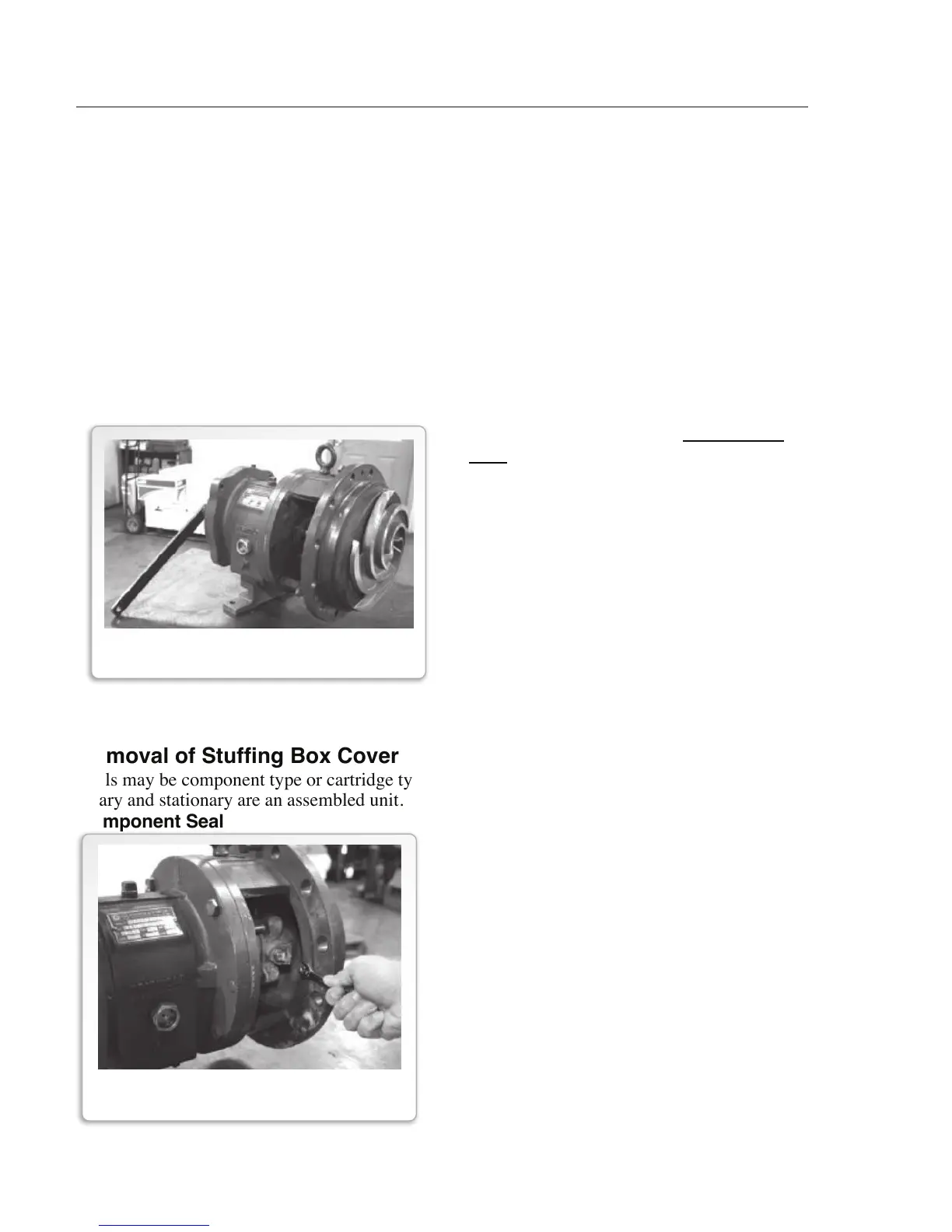
Removal of Stuffing Box Cover – Mechanical Seal Pumps
Seals may be component type or cartridge type. With a cartridge seal, the gland, sleeve and seal
rotary and stationary are an assembled unit.
Component Seal
1. Remove seal gland stud nuts (Item 355).
Separate seal gland (Item 250), and slide
gland toward bearing isolator (Item 333A).
2. Remove seal chamber stud nuts (Item 370H ).
3. To remove seal chamber (Item 184), slide
chamber forward and off of pump shaft.
4. Remove seal rotary together with shaft sleeve
(Item 126). Note that seal set screws may
have to be loosened. Remove seal rotary
from shaft sleeve. Slide seal gland with
stationary seat and o-ring gasket off of pump
shaft. Be careful not to damage the stationary
seat of the seal as it is located in the gland bore.
FIGURE 13
IMPELLER REMOVAL
FIGURE 14
STUFFING BOX COVER REMOVAL