GRISWOLD PUMP COMPANY Repair Maintenance Page 24
Installation, Operation and Maintenance Manual
Griswold Model 811
Griswold Pump Company Repair Maintenance Page 26
When pressing bearings off shaft, use force
on inner race only.
Power End Disassembly – S and M Group Pumps
1. Remove cap screws (Item 370C),
loosen jam nuts (Item 423).
2. Tighten jack bolts (Item 370D) evenly.
Bearing housing will begin to back out of
frame.
3. Slide shaft assembly, with bearing
housing out of bearing frame.
4. Remove all jackscrews and nuts (Item
370D) and (Item 423).
5. Remove and discard bearing housing o-
ring (Item 496).
6. Using snap ring pliers, remove bearing
retaining ring (Item 361A).
7. Remove bearing housing (Item 134)
from shaft by tapping the shaft with a
rubber mallet, driving the thrust
bearings and shaft assembly through
the housing. Do not remove lab seal.
8. Remove bearing lock nut (Item 136)
and lock washer (Item 382).
9. Using an arbor press, remove inboard
and outboard bearings. Slide snap ring off shaft after bearings have been removed.
10. Complete disassembly of bearing frame if required. Remove oil fill plug (113A), oil
sight glass (408N) and (4) oil mist/grease plugs (408H). Remove oil cooler inlet and
outlet plugs (408L) and (408M). On M models, remove frame foot attachment bolts
(370F).
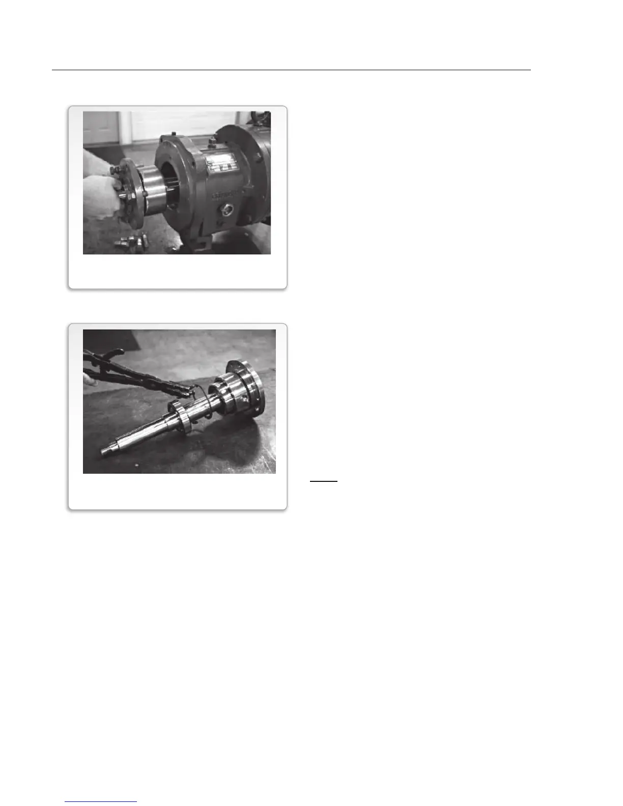
FIGURE 17
BEARING REMOVAL
FIGURE 16
SHAFT/BEARING HOUSING REMOVAL