 Loading...
Do you have a question about the Grizzly G0516 and is the answer not in the manual?
| Motor Power | 2 HP |
|---|---|
| Taper in Tailstock Spindle | MT #3 |
| Spindle Speed | 1200 RPM |
| Metric Thread Pitches | 0.2 - 3.5mm |
| Inch Thread Pitches | 8 - 56 TPI |
| Voltage | 110V/220V, Single-Phase, Prewired 110V |
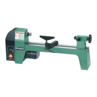
Essential safety guidelines for operating power tools, covering guards, clean work areas, and proper usage.
Specific safety precautions for using lathe and mill operations, including guards, workpiece security, and clothing.
Details on 110V operation, required fuse ratings, and circuit breaker considerations for the machine.
Guidelines for selecting and using appropriate extension cords, including gauge and condition requirements.
Ensuring proper grounding for safety, emphasizing correct outlet installation and plug usage.
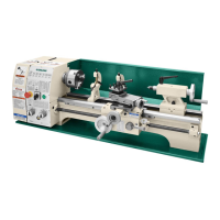
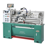
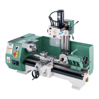
Overview of the Model G0516 Lathe/Mill and the purpose of the instruction manual.
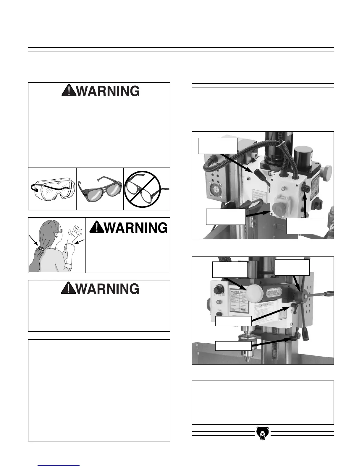
Identification of key controls and components on the lathe and mill sections of the machine.
Identification of essential accessories and tools provided with the Model G0516.
Steps and warnings for safely unpacking the combination lathe/mill from its crate.
List of all components and accessories found inside the shipping crate.
A guide to identify and match various hardware pieces during assembly.
Procedure for removing protective coatings and cleaning the machine parts before use.
Guidelines for floor load, working clearances, and lighting/outlets for optimal machine placement.
Initial assembly instructions, including installing the support leg.
Procedure for securely attaching the mill/drill unit to the main lathe body.
Instructions for mounting the backsplash to the lathe for protection.
Steps for attaching the safety eyeshield to the mill/drill head.
Procedure for performing an initial test run of the lathe to ensure proper function.
Procedure for performing an initial test run of the mill/drill to ensure proper function.
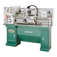
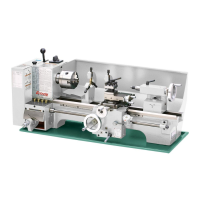
Introduction to lathe operations, controls, and components.
Step-by-step instructions for safely removing the chuck or faceplate from the lathe spindle.
Instructions for correctly installing a chuck or faceplate onto the lathe spindle nose.
Guide on how to install the MT#2 dead center into the tailstock barrel.
Steps for safely removing the dead center from the tailstock barrel.
Procedure for adjusting the tailstock's longitudinal position along the bed.
Instructions for removing and installing different tool posts on the compound rest.
Guide on how to adjust the cross slide for accurate movement and scale reading.
Procedure for adjusting the compound slide angle and handwheel scale.
Instructions for manually and automatically controlling the carriage movement.
Explanation of how to read turning and threading charts for feed rate and gear setup.
Detailed steps for changing gears to set specific carriage feed rates.
Procedure for setting up gears to perform left-handed reverse threading operations.
Instructions on how to change spindle speeds by repositioning V-belts on pulleys.
Introduction to mill/drill operations, controls, and components.
Procedure for removing and installing different chucks on the mill/drill spindle.
Steps for removing the compound slide and installing the milling table accessory.
Guidelines for lubricating machine components using specified oils and techniques.
Procedure for inspecting V-belts for condition and proper tension.
A template for recording maintenance activities and hours of use.
Information regarding factory adjustments and when to contact customer service.
Procedures for adjusting cross-slide, compound slide, saddle, and mill/drill gibs for optimal fit.
Steps for aligning the tailstock with the headstock for accurate operations.
Information about factory-set bearing preload and when to seek service.
A template for recording service performed and hours of use.
Detailed technical specifications, dimensions, capacities, and motor details for the G0516.
Electrical schematic illustrating the wiring connections for the lathe/mill.
Diagrams showing the exploded view of the machine components for identification.
Comprehensive lists of part numbers and descriptions for machine components.