G0603X 25" Extreme Series Planer
-37-
Table Parallelism Adjustments
The table is adjusted by turning the elevation
screw housing brackets underneath the table.
To adjust the table parallelism:
1. Adjust the table height so that the Rotacator
(or wood block and feeler gauges) can be
used.
2. DISCONNECT THE PLANER FROM
POWER!
3. Raise the headstock cover.
4. Using the cutterhead pulley, rotate the
cutterhead so that the carbide insert on the
left edge of the cutterhead is at bottom dead
center (BDC) (see
Figure 29)—this will also
place the carbide insert on the right side of
the cutterhead at BDC.
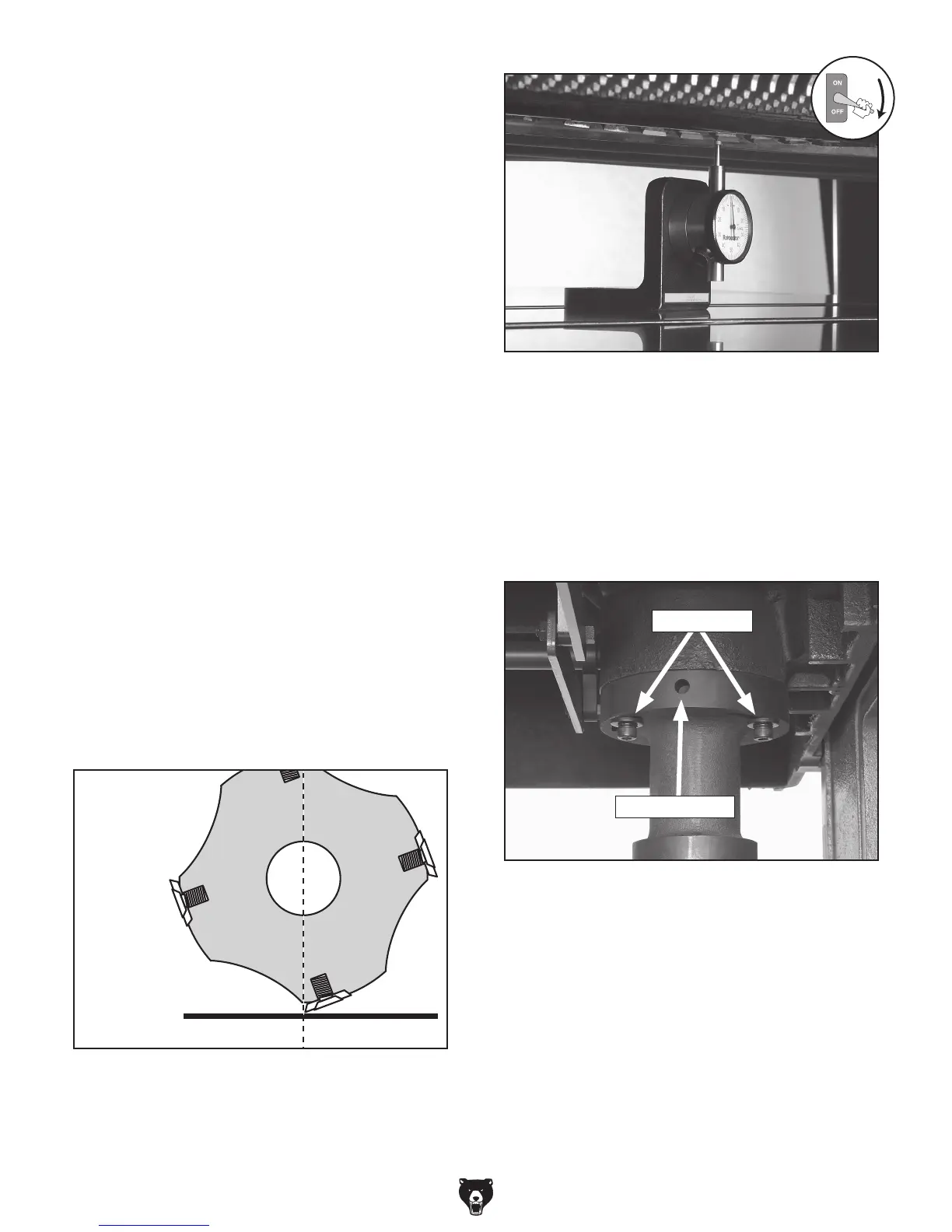
—If you are using a Rotacator, find BDC of
the carbide insert by slowly rocking the
cutterhead pulley back and forth, and set
the Rotacator dial to zero (see
Figure 30).
—If a Rotacator is not available, use a wood
block and a feeler gauge; then, slowly rock
the cutterhead pulley back and forth so
the carbide insert just makes contact as it
passes the feeler gauge.
Figure 29. Cutterhead carbide insert at bottom
dead center (BDC).
5. Determine which side of the table you will
adjust to bring the table parallel with the
cutterhead (within
0.003").
6. Use the 6mm hex wrench to loosen the table
elevation housing bracket cap screws (under
-
neath the table) for that side of the table (see
Figure 31).
7. Insert the long end of the 10mm hex wrench
into the leverage hole and turn the bracket
until you are satisfied with the table parallel
-
ism from side-to-side.
Note: The slight deformation of the rubber
elevation screw cover is normal and will not
affect table movement.
8. Retighten the cap screws holding the bracket
in place.
Figure 30. Finding BDC with the Rotacator.
Figure 31. Table elevation screw housing
bracket.
Leverage Hole
Cap Screws
 Loading...