-40-
G0603X 25" Extreme Series Planer
Adjust Depth Scale
Tools Needed: Qty
Hex Wrench 4mm ..............................................
1
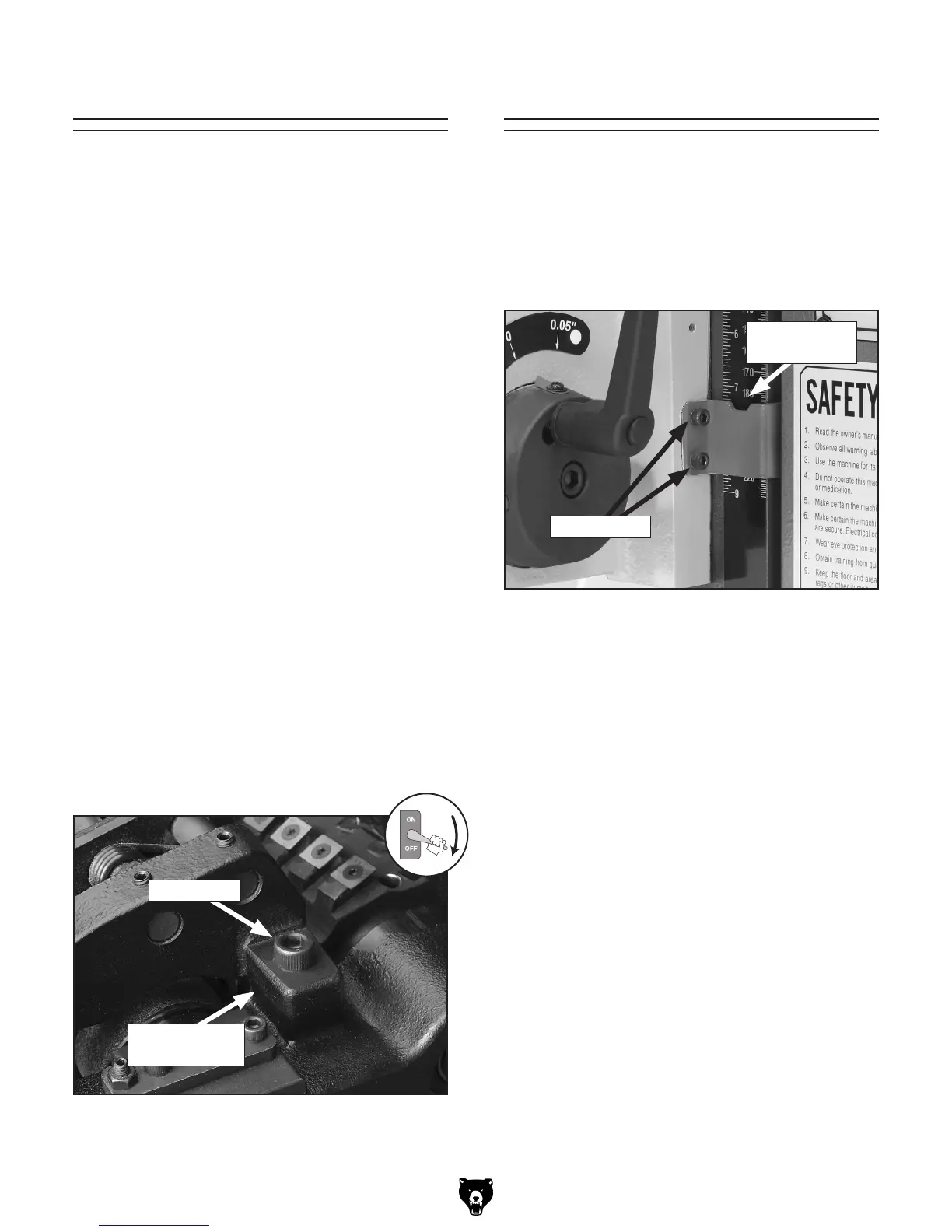
The pointer on the depth scale (see Figure 37
)
should indicate the same value as shown in the
bottom actual position LED window of the digital
control.
Figure 37. Depth scale pointer.
Cap Screws
Depth Scale
Pointer
Adjust Chipbreaker
Distance Below Cutterhead at BDC:
Chip Breaker .............................................
0.020"
Tools Needed: Qty
Rotacator ........................................................... 1
Hex Wrench 8mm .............................................. 1
Metal Shims ........................................ as needed
To set the height of the chipbreaker:
1. DISCONNECT THE PLANER FROM
POWER!
2. Follow the same methods for determining the
height of the chipbreaker in relation to the
cutterhead as detailed in the previous proce
-
dural block (reference
Page 38).
3. If an adjustment is necessary to bring the
height of the chipbreaker to the specification
listed above:
a. Remove the cap screws on each end of
the chipbreaker (see
Figure 36)
b. Place the required metal shim(s) between
the chipbreaker and the headstock cast
-
ing.
c. Replace and tighten the cap screws
removed in Step 3a
.
Figure 36. Chipbreaker mounting to headstock
casting (right side shown).
Cap Screw
Metal Shims
(if needed)
To adjust the depth scale pointer:
1. Loosen the two cap screws that secure the
pointer.
2. Adjust the pointer and retighten the cap
screws.
 Loading...