-38-
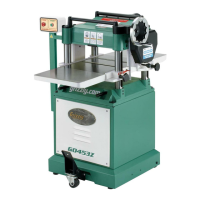
G0603X 25" Extreme Series Planer
Adjust Infeed/
Outfeed Rollers &
Pressure Bar
Distances Below Cutterhead at BDC:
Infeed Roller ..............................................
0.020"
Pressure Bar ....................................................
0"
Outfeed Rollers .........................................
0.020"
Tools Needed: Qty
Rotacator ........................................................... 1
Hex Wrench 8mm ..............................................
1
Wrench 8mm .....................................................
1
Wrench 14mm ...................................................
1
To ensure accurate results and make the adjust
-
ment process quicker and easier, we recommend
using a Rotacator (see Page 29) for these adjust
-
ments.
If a Rotacator is not available, wood blocks and
feeler gauges can be used.
To set the height of the infeed roller, pressure
bar, and outfeed rollers using a Rotacator:
1. Make sure the cutterhead and table are paral-
lel, and the cutterhead is at BDC. Reference
Table Parallelism on
Page 36.
Note: Zero the Rotacator dial after finding
the BDC of the cutterhead. This will ensure
that the following adjustments are accurate in
relation to the cutterhead.
2. DISCONNECT THE PLANER FROM
POWER!
3. Place the Rotacator under the right-hand
side of the infeed roller and find the BDC on
a serrated edge by sliding the Rotacator right
to left in a zigzag pattern—toward the front of
the planer, then toward the rear of the planer,
and so on.
4. Adjust the height of the infeed roller on the
same side as the Rotacator to the specifica
-
tion given at the beginning of this procedure,
using the zero setting of the Rotacator as a
reference point.
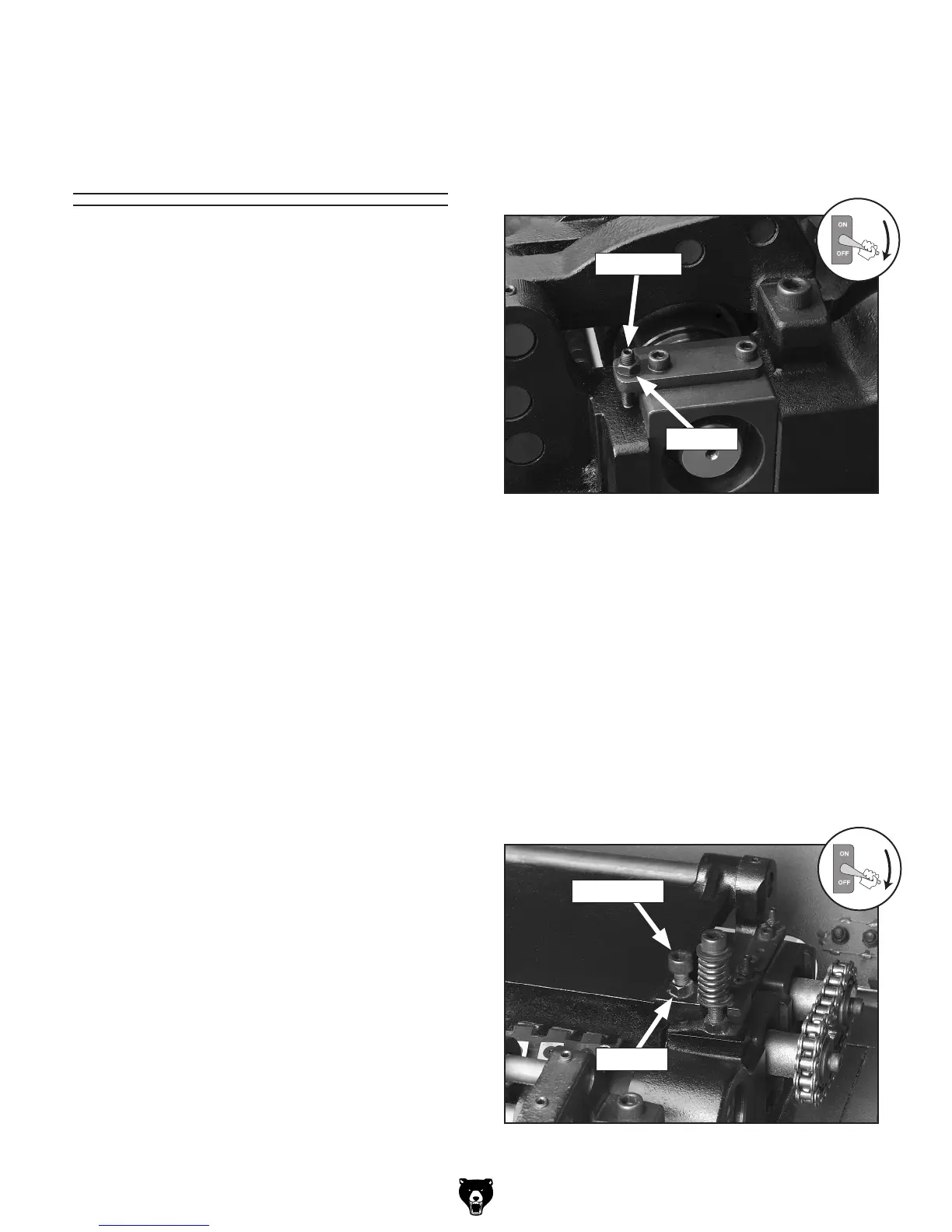
Figure 32 shows the jam nut
and set screw for adjusting the roller height.
Figure 32. Infeed jam nut and set screw (right
side shown).
Jam Nut
Set Screw
5. Repeat Steps 3 & 4 for the left-hand side of
the infeed roller.
Note:
You may have to repeat these adjust-
ments from side-to-side until the entire roller
height is correct.
6. Using the same zeroed reference on the
Rotacator, adjust the height of the pressure
bar and outfeed rollers to their given specifi
-
cations. The adjustment cap screw, jam nuts
and set screws are shown in
Figures 33 &
34.
Figure 33. Pressure bar jam nut and set screw
(one side shown).
Cap Screw
Jam Nut
 Loading...