-20-
Model G0771 (Mfd. Since 8/15)
8. Install end cap with (2) pre-installed tap
screws on left end of front fence rail (see
Figure 22).
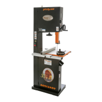
6. Insert connecting bar into long section of rear
fence rail and tighten set screws, then slide
short section of rail onto connecting bar and
tighten set screws (see Figure 20).
Figure 20. Rear fence rail assembled.
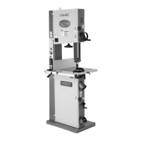
7. Remove (2) M8-1.25 x 16 hex bolts from
switch and insert into bottom slot on left end
of fence rail (see Figure 21). These will be
used later for mounting the switch.
Figure 21. Hex bolts for mounting switch.
x 2
Figure 22. Left end cap on front fence rail.
x 2
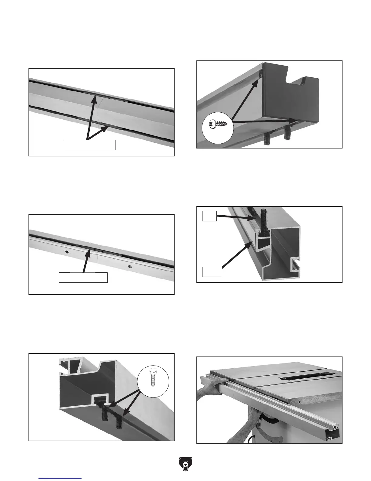
9. Orient fence rail so scale is facing you. Slide
(4) M8-1.25 x 30 hex bolts into slot on right
end of rail and (4) M8-1.25 x 30 hex bolts into
slot on left (see Figure 23).
Figure 23. Hex bolt positioned in front fence rail
slot.
10. Align hex bolts in fence rail with holes in
table, then insert bolts into table. Be sure
scale on fence rail is facing up. Hand tighten
(8) M8-1.25 hex nuts onto hex bolts. Do not
fully tighten yet (see Figure 24).
Figure 24. Mounting front fence rail.
Slot
Scale
5. Insert two connecting bars into long section
of front fence rail and tighten set screws, then
slide short section of rail onto connecting
bars and tighten set screws (see Figure 19).
Figure 19. Front fence rail assembled.
Connecting bars
Connecting bar
 Loading...