-32-
Model G0938 (Mfd. Since 03/21)
Checking/Replacing
Motor Brushes
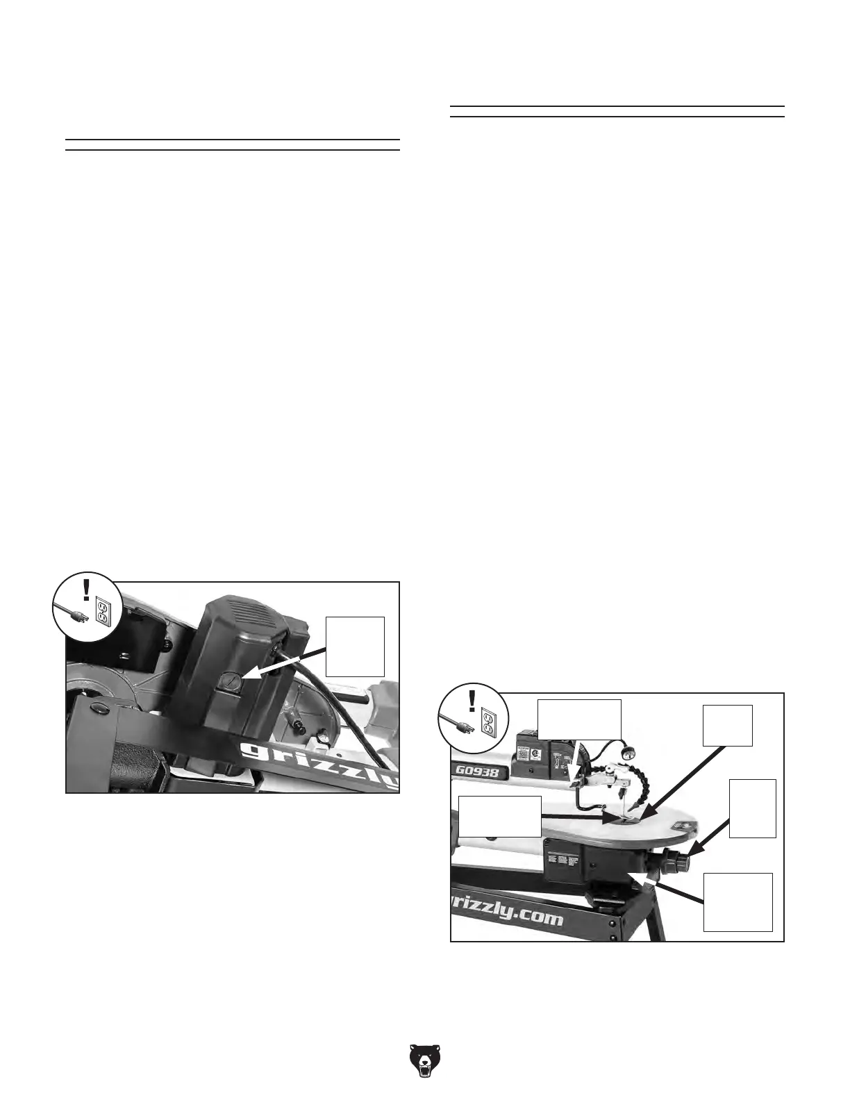
Figure 34. Motor brush location.
The motor on the Model G0938 is equipped with
two long-life carbon brushes—one on each side
of the motor. The brush life is affected by motor
loads and usage. Worn brushes will result in inter-
mittent operation and difficulty starting the motor.
If either brush is worn down to
1
⁄4" (6mm) or less,
replace both brushes as a set.
Items Needed Qty
Flat Head Screwdriver
1
⁄2" .................................. 1
Motor Brushes (P0938100-2)
............................ 2
To check/replace motor brushes:
1. DISCONNECT MACHINE FROM POWER!
2.
Unscrew plastic brush covers, and remove
motor brush assemblies (see Figure 34).
Note: As you remove brush assembly, make
note of carbon tip orientation. If acceptable,
re-install in same way.
3. Measure length of carbon tip. If carbon tip is
worn down to
1
⁄4" (6mm) or less, replace both
brush assemblies with new ones.
4.
Insert brush assemblies back into motor, and
re-install plastic caps.
Motor
Brush
(1 of 2)
Calibrating Table Tilt
The table tilt knob and tilt scale are used to posi-
tion the table for performing bevel cuts. Over the
life of the machine, the components may loosen
or stretch, at which point it will be necessary to
recalibrate the system to ensure accuracy.
Note: The table tilt scale is only an approximate
scale and should not be used when precise angle
measurements are required for the operation.
Tools Needed Qty
Phillips Head Screwdriver #2 ............................ 1
Adjustable Wrench
............................................ 1
Machinist's Square
............................................ 1
Locking Pliers
.................................................... 1
To calibrate table tilt:
1.
DISCONNECT MACHINE FROM POWER!
2.
Remove machine housing panel to access
table tilt adjustment cable (see Figure 35).
3.
Loosen hold-down lock knob and remove
hold-down shoe (see Figure 35).
4.
Remove table insert (see Figure 35).
5.
Loosen table lock knob and set table to a flat
position (see Figure 35).
Figure 35. Table tilt components.
Table
Insert
Hold-Down
Lock Knob
Hold-Down
Shoe
Table
Lock
Knob
Machine
Housing
Panel


 To Next Page