-30-
Model G7945/G7946 (Mfd. Since 09/17)
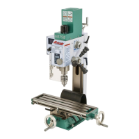
2. Loosen the lock bolt (Figure 31) using the
included wrench and tilt the table (G7945)
or the column support arm (G7946) to the
desired angle.
Adjusting Table Rotation
(G7946 Only)
1. Loosen the lock lever located under the table
(see Figure 32). Rotate the table the desired
amount.
2. Always lock the table support arm in place
before operating the machine.
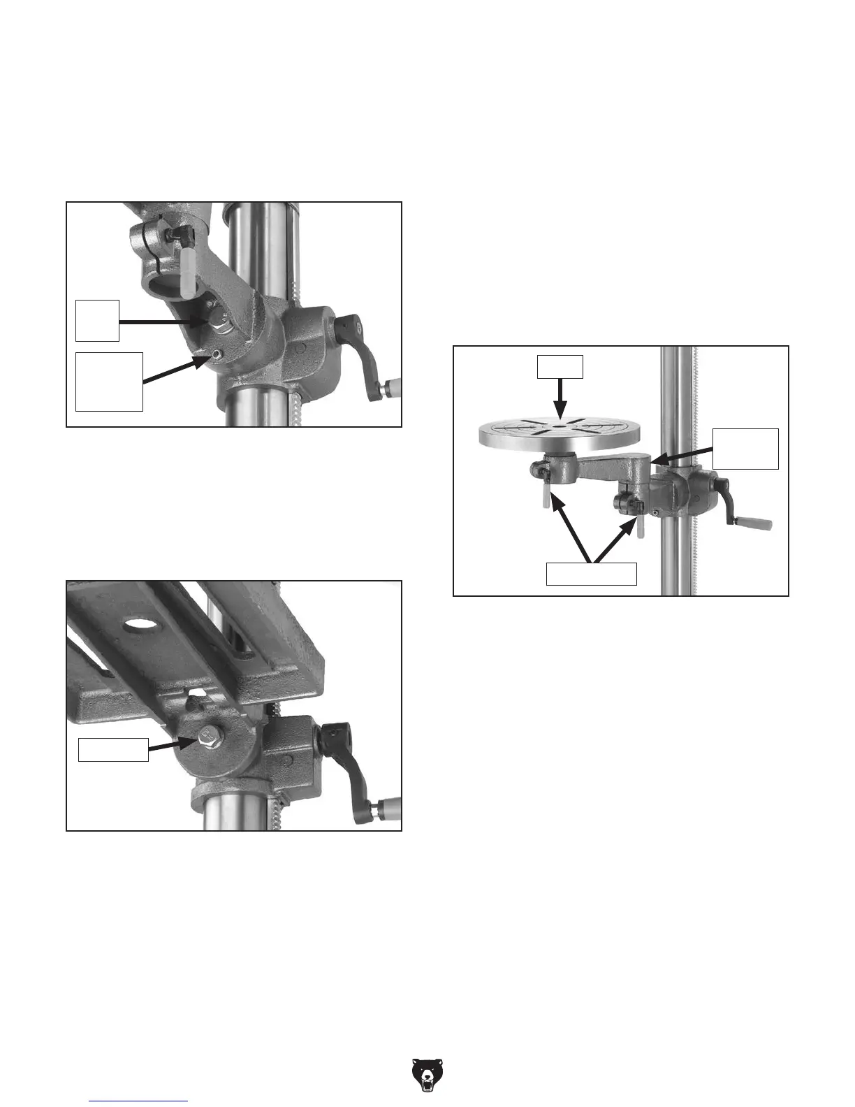
Adjusting Distance from Column
(G7946 Only)
1. Loosen the lock lever located at the pivoting
elbow of the table support (see Figure 32).
2. Swing the table support to the desired dis-
tance from the column. The support bracket
may need to be rotated around the column
to keep the table centered under the chuck.
Secure all lock levers before operating the
machine.
3. Lock in place by tightening the lock bolt.
4. (G7946 Only): To return the table to its
original position, align the holes in the column
support arm and table bracket, insert the
locating pin and nut, and gently tap the pin
with a hammer.
5. Tighten the locating pin nut.
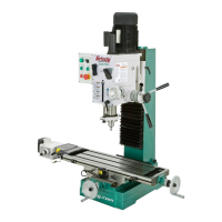
Adjusting Table Tilt
1. (G7946 Only): Turn the locating pin nut (see
Figure 30) in a clockwise direction
.
This will
draw the locating pin out of the casting. Once
loose, pull out the pin and nut, and set them
in a safe place until needed.
Figure 32. Adjusting distance from column.
Pivoting
Elbow
Table
Lock Levers
Figure 31. Table tilt lock bolt for angle
adjustment (G7945).
Lock Bolt
Figure 30. Table tilt locating pin and nut and lock
bolt for angle adjustment (G7946).
Lock
Bolt
Locating
Pin and
Nut

 Loading...