GROOMING MOWERS - SGM Series - Models SGM 48-60-72-84
22
Holding wheel and yoke assembly up, remove the lynch pin (B) from top of gauge wheel spindle
(C);
Position the spacers (A) as desired. The spacers are assorted with heights of 1/4''-1/2'' and 1'',
to allow adjustment at multiple levels of cutting heights (from 1” to 5”);
Replace the lynch pin on top of gauge wheel spindle;
Repeat the same for the other three wheels. Verify that the same amount of spacers are
under all 4 caster arms: only an equal adjustment ensure a completely uniform cut;
Remove safety block, than put mower down on the ground.
IMPORTANT:
Very low cutting heights should be avoided. Damaging shock loads occur when the blades strike
the ground. This can cause damage to the mower and drive.
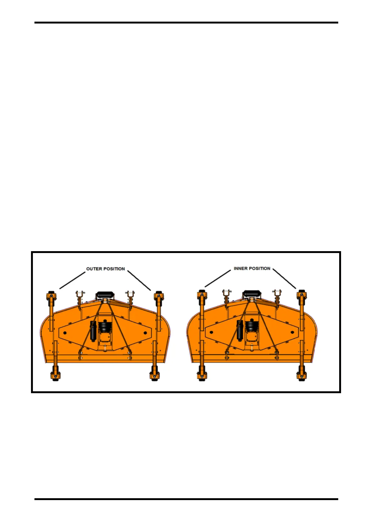
WHEEL ARM ADJUSTMENT
The front wheel arms of the SGM60-72-84 mowers (*) can be set in two different configurations:
Inner position (see picture below - left side), that allows the outside edge of the mower to be
used for trimming under shrubs or fences;
Outer position (see picture below - right side), that provides the most clearance to avoid inter-
ference with tractor tires.
To change configuration, do the following (see picture below):
Remove the screws (A), washer (B) and nuts (C) connecting the front wheel arm to the rail
(D) welded to the frame. To simplify the adjustment procedure, the belt cover (E) can be
removed from mower frame;
Move the arm (F) from one side of the rail to the other;
Position the arm according to proper own requirement, then secure them to the wheel rail
through the original hardware. Replace the belt cover if disassembled;
Repeat the procedure for the other front wheel arm.
 Loading...