21
English (US)
4. Use Grundfos R100 to set the Operating mode to Stop in the
operation menu.
5. Use Grundfos R100 to set the other displays as required for
the pump application (such as setpoint).
6. Disconnect the power supply to both pumps.
7. Installation of the AYB cable (91125604):
a. Remove the plug from each MLE terminal box with a flat
head screw driver. See fig. 31.
b. Screw a new cable gland into each MLE terminal box with a
crescent wrench. See fig. 31.
c. Loosen the new cable gland caps and push the cable ends
through the cable glands and into MLE motors.
d. Remove the AYB connector plug from the first MLE motor.
See fig. 32.
e. Connect the black wire to the A terminal of the AYB
connector plug.
f. Connect the orange wire to the Y terminal of the AYB
connector plug.
g. Connect the red wire to the B terminal of the AYB connector
plug.
h. Reconnect the AYB connector plug to the first MLE motor.
i. Tighten the cable gland cap to secure the cable. See fig. 31.
j. Repeat steps d to i for the second MLE motor.
8. Connect the power supply to the two pumps according to the
installation and operation instructions.
9. Use Grundfos R100 to check that the Operating mode is set to
Normal in the operation menu of the second pump.
10.Use Grundfos R100 to set the other displays as required for
the pump application (such as Setpoint).
11. Use Grundfos R100 to set the duty/standby to Active in the
installation menu of the second pump. Please note the second
pump will search for the first pump and automatically set the
duty/standby to Active in the installation menu.
12.The second pump will operate for the first 24 hours. The two
pumps will then alternate operation every 24 hours.
Fig. 31 Removing the plug and connecting cable gland to the
terminal box
Fig. 32 AYB connector plug
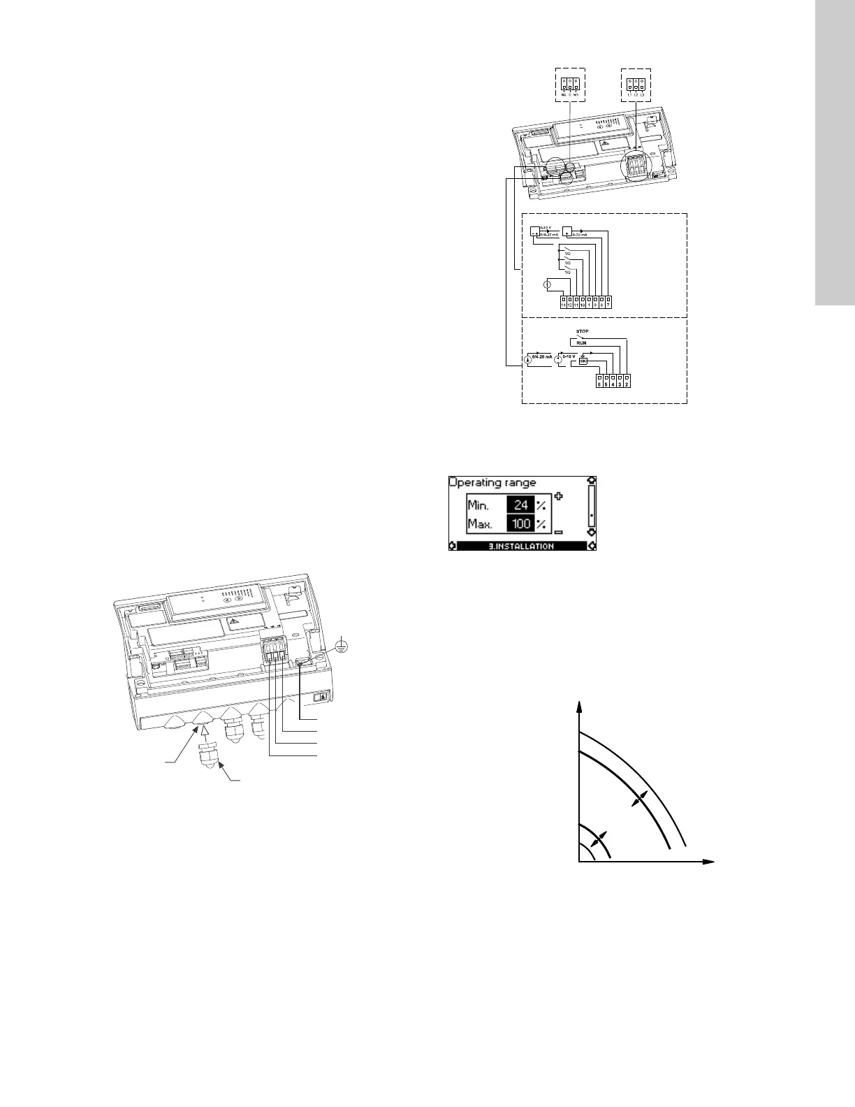
10.3.12 Operating range
How to set the operating range:
• Set the min. curve within the range from max. curve to 12 % of
maximum performance. The pump is factory-set to 24 % of
maximum performance.
• Set the max. curve within the range from maximum
performance (100 %) to min. curve.
The area between the min. and max. curves is the operating
range.
Fig. 33 Setting of the min. and max. curves in % of maximum
performance
TM05 1626 3311
TM05 2985 0812TM00 7747 1896
100 %
Max. curve
12 %
Min. curve
Op
e
rat
i
n
g
ra
ng
e

 Loading...


