10
2.1.1 Mounting the NEMA 1 terminal cover kit
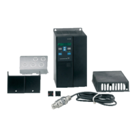
Mount the terminal cover for cable lead as shown
in fig. 7.
Fig. 7 Mounting the metal part
Mount cables to mains supply, motor, pressure
sensor and relay via conduits.
Mount the terminal cover as shown in fig. 8.
Fig. 8 Mounting the terminal cover
2.1.2 Access to control terminals
(pressure sensor or relay)
All control terminals are located underneath the pro-
tective plate on the front of the CU 321. Remove the
terminal cover to make it possible to remove the
protective plate. Remove the protective plate by slid-
ing it downwards, see fig. 9.
Fig. 9 Accessing the control terminals
2.1.3 Mounting the top cover
Mount the top cover as shown in fig. 10.
Fig. 10 Mounting the top cover
TM03 2629 4505TM03 2630 4605
TM03 6006 4106
TM03 5995 4106