8
1.5 Positioning the pressure sensor
Pressure losses often cause inconvenience to
the user.
The CU 321 keeps the pressure constant in the
place where the pressure sensor is positioned,
see fig. 5.
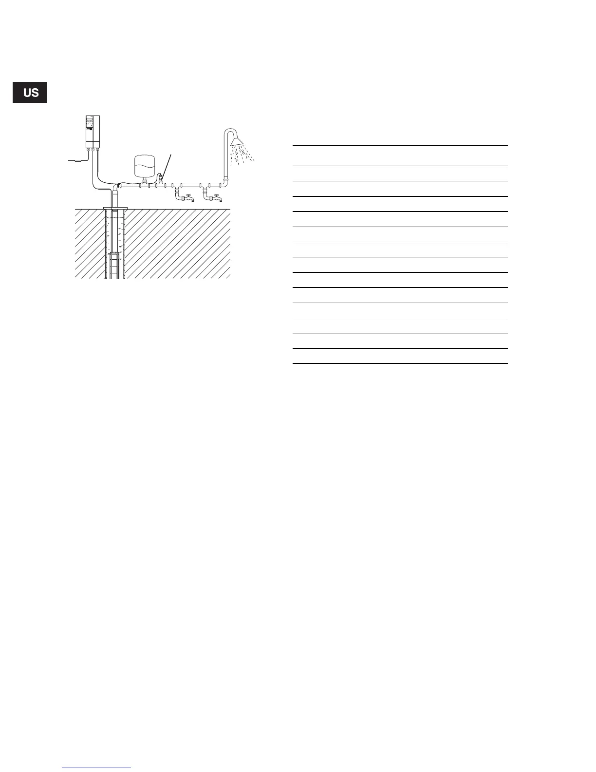
Fig. 5 Pressure sensor position
In fig. 5, tap 1 is placed close to the pressure sensor.
Therefore, the pressure will be kept nearly constant
at tap 1, as the friction loss is small. At the shower
and tap 2, the friction loss is greater. This depends
on the piping.
It is recommended that the pressure sensor be
positioned as close to the places of consumption
as possible.
1.6 Precharge pressure setting
The CU 321 is designed to work with a 4 gal.
(minimum) diaphragm tank.
The precharge pressure of the diaphragm tank must
be set to 70% of the pressure setting in order to use
the tank to the limit of its capacity. This is especially
important when the tank volume is limited to 4 gal.
Use the values in the following table. Precharge
pressure is measured with 0 psi in the pipeline:
TM03 2617 4605
Pressure sensor
Tap 1
Tap 2
Shower
CU 321
Setting [psi] Precharge pressure [psi]
40 28
45 31
50 35
55 38
60 42
65 45
70 49
75 52
80 56
85 59
90 63
95 66
100 70