7
System limits
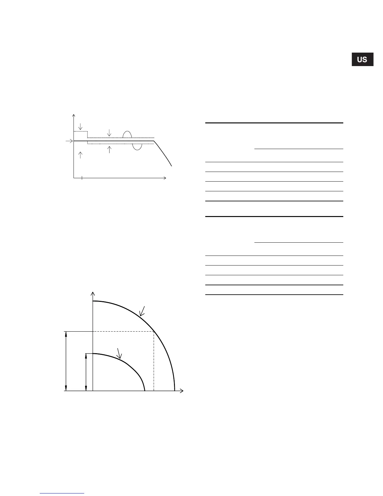
Even though the CU 321 is controlling the pressure
within ±3 psi, larger pressure variations may occur in
the system. If the consumption is suddenly changed,
e.g. if a tap is opened, the water must start flowing
before the pressure can be made constant again.
Such dynamic variations depend on the pipework,
but, typically ±7 psi. If the desired consumption is
higher than the quantity the pump is able to deliver at
the desired pressure, the pressure follows the pump
curve as illustrated in the far right of fig. 3.
Fig. 3 Pressure as a function of the flow
Note: The pressure may fluctuate up to 20 psi below
the setpoint when the pump is started in a high-
demand situation. A larger diaphragm tank will mini-
mize this effect.
1.4 System sizing
To ensure the correct function of the system, it is
important that the pump is of the right type.
During operation, the CU 321 controls the pump
speed within the range from 1,500 to 3,600 rpm,
see fig. 4.
Fig. 4 Pump curve (sizing)
Recommended guidelines for system sizing:
The following must be fulfilled:
• Min. head at no flow < static head + system
pressure.
Comment: If this is not fulfilled, the pressure may
exceed the pressure set on the CU 321.
• Max. head at rated flow > dynamic head + system
pressure.
Comment: If this is not fulfilled, the pressure may
fall below the pressure set on the CU 321.
Max. head at rated flow and min. head at no flow can
be found in the table below:
3 hp:
5 hp:
TM03 3601 0406TM01 8547 0400
Controlling
±3 psi
Dynamic
variations
±7 psi
Pressure
Start at
setpoint
Stop
+7 psi
gpm
0.8